Measure time between Inputs

gybugy

Member
Join Date
May 2020
Location
Australia
Posts
5
Hi, I am very new to using PLCs and am having a bit of trouble.

I need to measure the time between two proximity switches being turned on. I'm not sure how to achieve this in ladder logic. I'm using CX-Programmer for an Omron PLC if that helps.
 
Welcome to the forum.
We get a lot of requests for help with homework which most people are happy to help with as long as the person asking is willing to do and show their work. In other words, no one is going to do the homework for anyone but we are very willing to help people figure it out.
So with that, if this is homework, or for that matter even if it's not but in the interest of helping you learn, what have you tried so far (please show the work or describe what you've tried)?

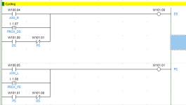
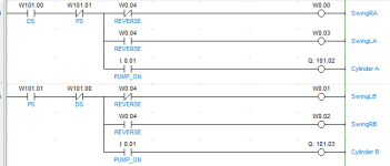
Hi, I'm trying to develop a program for a concrete pump. As we are looking at switching from using phsyical relays to a PLC (To avoid the physical problems we regularly experience with relays.)

Two pistons are cycling as the pump is on. I am controlling the cycling with the Pistons hitting a proximity switch. I am basically trying to time the entire cycle and send that time somewhere else.
I have thought about possibly using a counter with pulse bits to which are turned on when the proximities turn on. However being able to stop that after one cycle (of the pump) is beyond me.

Cycling 1.PNG Cycling 2.PNG
 
Hi, I'm trying to develop a program for a concrete pump. As we are looking at switching from using phsyical relays to a PLC (To avoid the physical problems we regularly experience with relays.)

Two pistons are cycling as the pump is on. I am controlling the cycling with the Pistons hitting a proximity switch. I am basically trying to time the entire cycle and send that time somewhere else.
I have thought about possibly using a counter with pulse bits to which are turned on when the proximities turn on. However being able to stop that after one cycle (of the pump) is beyond me.


What PLC are you using?


E.g. MicroLogix 1100 has a free-running 10kHz clock counter, and also the number of 10kHz cycles between scans, in various status words. You'd have the usual accuracy issues, but it would be reasonably close.
 
Hi, I'm trying to develop a program for a concrete pump. As we are looking at switching from using phsyical relays to a PLC (To avoid the physical problems we regularly experience with relays.)

Two pistons are cycling as the pump is on. I am controlling the cycling with the Pistons hitting a proximity switch. I am basically trying to time the entire cycle and send that time somewhere else.
I have thought about possibly using a counter with pulse bits to which are turned on when the proximities turn on. However being able to stop that after one cycle (of the pump) is beyond me.


Like this?


https://www.youtube.com/watch?v=MrfySTiwoOc


Also, what is the approximate time you are trying to measure (ms; s; minutes)? And to what accuracy?
 
Last edited:
What PLC are you using?


E.g. MicroLogix 1100 has a free-running 10kHz clock counter, and also the number of 10kHz cycles between scans, in various status words. You'd have the usual accuracy issues, but it would be reasonably close.

We're using an OMRON CP1L at the moment.
 
Yep exactly like that. I'm trying to measure the time it takes between both sides to complete a stroke each.


so one full cycle i.e.


  1. start at a state e.g rising edge on piston 1 prox
    1. somehow mark that as "zero" time
  2. wait for next occurrence of that same rising edge on piston 1 prox
    1. somehow mark that as "end" time
  3. Subtract "end" time from "zero" time
I know bupkis about OMRON, but there must be some sort of timing parameters and/or status words that say summat about time.


It looks like CPU1L has internal clock pulses, up to 50Hz, that you could count: https://assets.omron.eu/downloads/manual/en/v2/w462_cp1l_cpu_unit_operation_manual_en.pdf#G9.1027794
 
Last edited:
I would continuously measure every cycle and put each measurement into a circular buffer of 100 or 256 or 1024 measurements, so I could get an idea of mean and standard deviation. But that's me.


You want one measurement, presumably on demand (e.g. press a button to make a new measurement). There will be three states:


State 1) on-demand button was pressed,

  • Assign zero to counter (any integer)
  • Waiting for next trigger: rising edge on piston 1 prox AND in state 1
    • On that trigger, Assign 2 to state
State 2) piston 1 prox occurred while in state 1,

  • Counter increments by one (++ instruction) on each 50Hz rising edge
  • Waiting for next trigger: rising edge of piston 1 prox AND in state 2 AND counter greater than zero
    • On that trigger, assign 3 to state
State 3) piston 1 prox occurred while in state 2

  • Accumulated counter pulses are put on display
  • Waiting for next trigger: rising edge of on-demand button press
    • On that trigger, assign 1 to state
This is far from the best approach, but it is simple and robust: three states, with a clear trigger for each and transition to the next.


The blue AND clause is important or else it could move from state 1 to state 3 in one cycle, although that can be avoided by reversing the order of the trigger tests.


Also, the button press rising edge trigger should probably not care what state the measurement is in, but that trigger should always initiate state 1.

Thankyou mate, I'll give it all a try and let you know if I have any troubles!
 
just thinking:


The way I wrote it there, the count will be set to 0 on every scan in state 1 until the trigger to state 2.
Likewise in state 3 (it will keep updating the display, if such is used). It will still work that way, but it feels messy.


So, depending on your level of OCD (mine is fine and active, thank ye very mooch;)), maybe old state 1 becomes state 10, and the algorithm is only in state 10 for one scan because it advances to state 11 after assigning 0 to the counter, and that state 11 is where it waits for the first prox rising edge. Old state 2 becomes 20, and 20 transitions to 30 (old state 3) on the next prox rising edge, and 30 advances to 31 after displaying the accumulated count, and 31 is the inactive state, where it stays after that, doing nothing i.e. no code tests for state 31 (so it does not have to be 31; it could be 0 or 42 or -32767 or whatever).


And a button press rising edge always initiates the process by transitioning into state 10, even if it's another active state.
 
Last edited:
Assuming Button being used to initiate a one off capture of the time then on button press latch a bit, AND that bit with one shot falling of Cyl1 Back PX
To reset count and enable counter and count using some time pulse(s) when one shot rising from Cyl2 Back PX store count value, reset latch. Simple.
For continuous readings then ignore button, latch a bit to reset & enable count, reset on cyl2 Back PX.
 
In the downloads AB section there is a program MPH Between 2 Sensors

This measures the time between 2 inputs and then calculates the velocity, but the first half might fit your application.
 
In the downloads AB section there is a program MPH Between 2 Sensors

This measures the time between 2 inputs and then calculates the velocity, but the first half might fit your application.


OT: heh, I did this for a guy using Visual Basic and a National Instruments four-channel vacuum sensor for measuring slug flow velocity when cleaning a dairy system after milking; the same tool could also characterize the pulsator (milker) behavior. Fancy plots 'n all. Of course, that was two decades ago.
 

Similar Topics

I want to measure the execution time between two points in a Omron CJ1H-H PLC. This option is in the same screen as the screen where you view the...
Replies
8
Views
4,521
Greeting experts! We have a new machine we just built. It is equipped with regenerative drives. The machine uses Beckhoff controls (PLC and...
Replies
6
Views
1,084
Hey all. I have decided, for my own curiosity, that i want to know, and chart, exactly how much power my air conditioner actually consumes. And...
Replies
13
Views
1,621
Hello to all, I don't have to much experience in the PLC. I'm using the Studio 5000 v32.03 We are trying to measure the length of a product, in...
Replies
3
Views
1,119
For part of our test system, we need to measure water level inside a chamber, which is under vacuum. We were successfully using one of these by...
Replies
112
Views
28,157
Back
Top Bottom