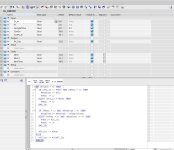
Explanation of How this SCL code works

qwemx

Member
Join Date
Jul 2017
Location
Earth
Posts
195
Dear Experts,

Need help understanding this SCL code .

IF (#SimOn = 0) THEN
IF (#DI_In <> #Mem) AND (#Mem1 = 0) THEN
#RemTime := #Tf;
#Mem1 := 1;
ELSIF (#DI_In = #Mem) THEN
#Mem1 := 0;
END_IF;

IF (#Mem1 = 1) AND (#RemTime > 0) THEN
#RemTime := #RemTime - #SampleTime;
ELSIF (#Mem1 = 1) AND (#RemTime <= 0) THEN
#Mem := #DI_In;
#Mem1 := 0;
END_IF;

#PV_Out := #Mem;
ELSE
#PV_Out := #SimPV_In;
END_IF;
 
first, without the complete code including the headers it's not very clear what the variables mean or what type they are.
second, this seems not to be the most complicated code... maybe ask what you are not understanding about it?
 
From the manual provided it is a filtered digital input.
The input has to be on for more than Tf/SampleTime scans before the output turns on

It doesn't use timers but relies on the program cycling at a sample rate.

It is effectively a TON without timers.
 
delayed input with selectable simulation

It is easier to undestand if you look online view and change variables SimOn, SimPV_in, DI_in and look variables remtime and PV_out
 

Similar Topics

Hello all, A little background. Our organization is exploring using the Siemens S7 1500 PLCs in the future. We are an Allen Bradley's house...
Replies
16
Views
1,954
Good afternoon guys, hope y'all are doing well. Could someone explain how the wiring works on this card? From my research, each output is...
Replies
5
Views
2,257
Dear all, I am new to Allen Bradley PLCs and I have the following question. I want to know where to find a clear explanation of the register...
Replies
0
Views
1,075
Hello automation experts, I kindly ask your help about the pneumatic valve shown in the attached image. The valve is 3/2 which means it should...
Replies
9
Views
2,914
Hello experts, can you please help me understand the meaning of symbols shown in the attached pictures? First is U/S (I guess U represents...
Replies
6
Views
1,935
Back
Top Bottom