You are using an out of date browser. It may not display this or other websites correctly.
You should upgrade or use an alternative browser.
You should upgrade or use an alternative browser.
Flow totalizer
- Thread starter jpmorasse
- Start date
drbitboy
Lifetime Supporting Member
@sparkie et al.: yes, dedicated hardware would be much better in the real world.
OP (@jpmorasse; see below ): this is an interesting exercise for learning PLC programming, but for the reasons @sparkie mentioned, and others, one would be unwise to do totalizing in PLC beyond as an exercise. That said, if you stick with this, we folks here will very likely be able to help you. However, if you never post again, then you will be just like all the others and our widdle hearts will be broken (sniff sniff
 ).
).
Issues (our story so far)
P.S. The correlation between the image below and OPs moniker is meant for humor only, not as an insult. Think Br'er Rabbit.
OP (@jpmorasse; see below
Issues (our story so far)
- @parky and others: scaling is suspicious
- @Steve Bailey and others: 36 extra ticks per 100cs is suspicious
- @drbitboy and others: integer vs. floating point math in totalizer formula
P.S. The correlation between the image below and OPs moniker is meant for humor only, not as an insult. Think Br'er Rabbit.

durallymax
Lifetime Supporting Member
The p2k analog modules are 16 bit, In.Max should be around 65536.
The SCL instruction works with Floats as well if you want more resolution.
If you want to sample every 1 second there's an 2 second system bit that turns on for 1 second and off for 1 second. An NOE or'd with an NCE can give you 1 second samples. How much drift an error there would be with that I have no idea. For less precise things it works well as it removes the timer.
wOw This is way more answer and help than I expected  this is so nice!
I remove the logic using Pulse_Current. You all where right the Timer was never reseting. So now using the Pulse_Done it's looking like it's working.
Parky, For my personal information can you explain me what are IEC times and IDE?
Hooo I thought my module was 32Bit but it's actually 16bit. Thanks you to have spot it
Hahahah I never did made that researche before and It's really funny! Yesterday night I was for sure confuse and overwhelm
Thanks to you yo put me on the right road I thought It was a 32bit module...
Thanks to let me know about this bit I'll give it a try
About the application, it's for a brewing equipment. When we start the brew we need to add a calculated volume of water(+-5l). The totalizer will never get pass 1000L so I think the error that could came over time from the integration will not be an issue for this application.
So With all your comment I came back with this new program and to problem look like it's solve.
I'll now try to improve it so any hint or comment is more than welcome.
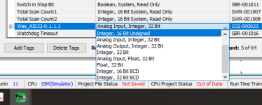
Also I'll like to find documentation about the type of ''value'' found in PLC's. Like in the shown picture(Float, integer, BCD?)
:site:
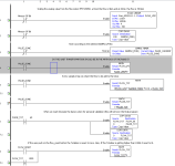
I suspect the timer will not reset until it reaches 150 (1.5 Secs), I doubt the timer will reset on putting a zero into the accumulated word (pulse_Current) It seems to be an IEC timer & I have tried on a couple of IDE's & it will not reset the timer until the 1.5 secs is up, however, not used this platform so cannot be sure.
I remove the logic using Pulse_Current. You all where right the Timer was never reseting. So now using the Pulse_Done it's looking like it's working.
Parky, For my personal information can you explain me what are IEC times and IDE?
We cannot see the status of the scale block, the min/max seem unusual never had an analogue use such high values but then they could be 32 bit conversion, also as op is using simulator it looks like he is putting a fixed raw value into the scale block has the op got the value correct for 60 LPM The max value
is 2,147,483,647 Really ????
That works out at 14,316,548.933 per litre so the value in the raw analogue would be 858,992,936 or do my eyes deceive me.
13,107 is correct for 4ma but the max input should be 65,535 according to the document, so where he got that value from I have no idea.
Hooo I thought my module was 32Bit but it's actually 16bit. Thanks you to have spot it
I've got much agreement with what has been posted. My answer is to use a pulse output meter and count the pulses. I try to avoid integrating 4-20 milliamp stuff whenever I can.
@sparkie et al.: yes, dedicated hardware would be much better in the real world.
Yes next time I'll bought a flow meter for a totalizing application I'll go for something more appropriate thant 4-20mA. Probably the learning curve that hitting me
OP (@jpmorasse; see below): this is an interesting exercise for learning PLC programming, but for the reasons @sparkie mentioned, and others, one would be unwise to do totalizing in PLC beyond as an exercise. That said, if you stick with this, we folks here will very likely be able to help you. However, if you never post again, then you will be just like all the others and our widdle hearts will be broken (sniff sniff
).
Issues (our story so far)
All in all, not a bad puzzle to spend time on for a Sunday afternoon during a pandemic waiting on the Super Bowl to start.
- @parky and others: scaling is suspicious
- @Steve Bailey and others: 36 extra ticks per 100cs is suspicious
- @drbitboy and others: integer vs. floating point math in totalizer formula
P.S. The correlation between the image below and OPs moniker is meant for humor only, not as an insult. Think Br'er Rabbit.
View attachment 57242
Hahahah I never did made that researche before and It's really funny! Yesterday night I was for sure confuse and overwhelm
The p2k analog modules are 16 bit, In.Max should be around 65536.
The SCL instruction works with Floats as well if you want more resolution.
If you want to sample every 1 second there's an 2 second system bit that turns on for 1 second and off for 1 second. An NOE or'd with an NCE can give you 1 second samples. How much drift an error there would be with that I have no idea. For less precise things it works well as it removes the timer.
Thanks to you yo put me on the right road I thought It was a 32bit module...
Thanks to let me know about this bit I'll give it a try
About the application, it's for a brewing equipment. When we start the brew we need to add a calculated volume of water(+-5l). The totalizer will never get pass 1000L so I think the error that could came over time from the integration will not be an issue for this application.
So With all your comment I came back with this new program and to problem look like it's solve.
I'll now try to improve it so any hint or comment is more than welcome.
Also I'll like to find documentation about the type of ''value'' found in PLC's. Like in the shown picture(Float, integer, BCD?)
:site:


durallymax
Lifetime Supporting Member
Also I'll like to find documentation about the type of ''value'' found in PLC's. Like in the shown picture(Float, integer, BCD?)
If I understand your question correctly, you're looking for a description of the different data types?
Integers are whole numbers. Signed integers can be negative or positive. Floats have a decimal place. BCD codes each decimal number into 4 binary bits. 765 would be 0111 0110 0101. 765 is normal binary is 0010 1111 1101.
That selection may also be where some of the scaling confusion showed up. Psuite offers analog in as either 32 bit int or float, but the actual resolution is limited to the hardware. Most p2k and p3k modules are 16 bit, while most p1k are 13bit.
The difference between IEC & standard timers is a difficult one, however, originally PLC's had built in functions for timers, these were often simple ones i.e. the timers had three parameters, the timer enable, the time set point & the timer done bit, some did have an extra parameter the accumulated time like AB for example, The IEC standard came up with timers that encompassed all the above, so many PLC manufacturers rather than re-designing the PLC's (to keep IEC standard) they wanted the IDE (Integrated development environment or if you like the program that you use to write the code) to be able to program the older models, although Rockwell (AB) decided on a complete new platform. so some PLC's give you the IEC types of timers but when it compiles the code uses the existing timers but with what could be considered enhancements but is really only extra code. In actual fact Mitsubishi do not use the on-board timers as such, the on-board timers are fixed when you give it the timer number, so for example T22, the IEC creates code that jumps to a subroutine that uses a special range of timers and temporary variables & returns the results (told you it was a bit complex).
The idea of IEC standards was for code that could be used on any PLC platform Structured text is a good example of this, so the IDE of any PLC type can import & use the source code.
Originally PLC's had fixed areas of internal variables for example AB had "B" for bits, "N" for integers "F" for floating point or reals etc. so when you used one of these you entered the address like N7:0, N7:1 etc. then gave it a symbol (Name), because of the IEC standard if you wanted to use the code in another PLC you would have to go through and edit all the physical addresses, using tag (symbol) based means the compiler allocates addresses to them when compiled, so in reality the address space for these symbol based tags are essentially the same but referenced by the tag name rather than actual address, some still use the address space but this is assigned at compile time, so for example in Mitsubishi you create a tag called My_Tag and it knows what type i.e. bit and assigns one of the real addresses to it i.e. M100. Sorry for the long winded explanation but as you get into other PLC's you will find this out.
On another note, Most flow meters have both analogue & digital outputs, however, the one you are using only has analogue the accuracy is limited anyway so I don't think your code is going to make it any worse, most flow meters I have used cost £1000.00 plus.
I have done many batching systems so I suggest the following steps.
1. On start of batch zero the accumulated total.
2. initiate the count (whatever way you do it).
3. Compare the actual with the required.
4.complete the sequence i.e. stop the flow (often you will use an in-flight to allow for time for valve or pump to stop).
5. end of sequence
So a good way to start before you write any code write down the sequence of events, then code it.
Here is a simple sequence for a bin load & tip sequence.
In this case an operator presses the start button and if a bin is in position at the fill station it fast fills the bin until the level reaches 80%, then the sequence steps on to slow fill until 100%, the sequence steps on to move the bin along a conveyor until it is detected at the lift/tip station, the sequence steps on to raise the bin until it reaches the top, the sequence steps on to tip the bin, and so on.
Here you can see I'm using an integer variable as the step sequence number and using this word to enable the logic to control the process, by comparing the sequence value with fixed steps (note this can be done not only as a sequence number but also as a range of numbers i.e. if a motor needs to run between sequence number 10 and 30 then you just use CMP => 10 AND CMP =< 30 so the motor runs while the sequence number is between 10 and 30. Note I use steps of 10 or more so that if I need another step in between I can just add it. It is also easy to step back from a sequence just by say for example at step 50 if something alters I can step back to 20 with the logic. at the end of the sequence it steps back to 10 to start it again.
This is just one way, you could use bits to step but I find this way far more flexible. Also if you have an HMI on the system using the variable for the step number you can display messages on the screen of what it is doing, many HMI's have a message field that when a value in the variable is present it displays a message for example if the variable sequence word contains 10 then the message displayed is "FAST FILLING" and so on.
drbitboy
Lifetime Supporting Member
...So With all your comment I came back with this new program and to problem look like it's solve.
I'll now try to improve it so any hint or comment is more than welcome.
:site:
Summary: the approach taken to implement a repeating timer matters
By changing from a [NO PULSE_DONE] during the same scan, to [NC PULSE_DONE] on the next scan, to implement a repeating timer, it takes an extra scan each second, which is not counted in the formula. Depending on the program this could be a fraction of a millisecond, or up to 10ms or more, per timer repeat. In the OP case, a 1ms scans give a 1ms error per repeat of ~1s, which would let an extra 0.1% volume per second flow into the vat, or 1l error per 1kl totalized. For 10ms per scan, it would be 1% and therefore 10l error per 1kl totalized.
Also, the PLC program makes the calculation only during a program scan, and PLC timing is neither deterministic nor guaranteed to start a progam scan exactly when the 100cs timer completes. So, even with a repeat-via-RESET timer (see experiment below) to eliminate the error described in the paragraph above, there will always be some extra time beyond the preset that is not included in the formula, probably averaging half a scan per repeat; that would be another 0.5l error per 1kl totalized for a 1ms scan time, which, added to the 1l error above is now 1.5l, or 30% of the +/- 5l error budget.
Now, I know I am messing about in the third and fourth significant digits here, but the error bedget is set between the second and third. And it's easy to fix the larger part of the error by changing how the repeat is implemented. In addition, @durallymax provided a method that uses a free-running clock to eliminate all scan-time-driven per-repeat error. I also did some experiments with that basic idea a while back, see here: https://github.com/drbitboy/PLC_2s_lamp_flash
Caveat
- This does not address errors resulting from inaccuracies in either the flowmeter or in the PLC internal clock.
Background and experiment
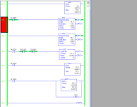
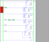
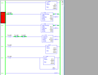
For example, see the images below, based on similar code in a MicroLogix 1100.
- S:4 is a 16-bit signed integer counter driven by a 10kHz Free-Running Clock (FRC)
- The FRC value is copied into 16-bit signed integer N7:0 at the start of each scan
- The actual FRC value, in S:4 and N7:0, is more or less irrelevant on any one scan, other than for comparison with another FRC value from a different scan
- The program runs two timers:
- Both timers have a preset of 1000cs, i.e 10s instead of 1s, to make it easier to watch what is happening.
- T4:0 is set to repeat using the [NC T4:0.DN] on the input rung (0001) of the timer
- T4:0 here is equivalent to PULSE_DONE in OP's program
- So this method for a repeating timer is probably the same as the OP program
- T4:1 (Rung 0002) is set to repeat using the [NO T4:1/DN] => [Reset T4:1] sequence on Rung 0005
- This is an alternate method for a repeating timer; OP used this in post #1 of this thread.
- The FRC value for a scan
- is MOVed to N7:1 on that scan when T4:0/DN is 1 i.e. when the /DN-rung-repeat timer completes
- is MOVed to N7:2 on that scan when T4:1/DN is 1 i.e. when the /DN=>Reset timer completes
- So if the timers start on the same scan and then complete on the same scan, the values in N7:1 and N7:2 will always be the same.
- The first image shows that, 10s after the scan when the program, and both timers, start, both timers completed on the same scan, because
- both completions MOVed the same value (-31067) into N7:1 and N7:2,
- also, the counter on Rung 0003 is 0, meaning the /DN bits were always the same up to the point that the image was taken.
- For the bitheads among us, assuming the the FRC value in S:4 was 0 on the first scan, that value (-31067) is equivalent to (32768*4-31067) = 100,005 ticks of the 10kHz FRC, or 10000.5ms = 10.0005s.
- The next image show that, after that, the two /DN bits have not been 1 on the same rung nine times:
- See the counter in rung 003.
- Also see the difference in the FRC values MOVed to N7:1 and N7:2.
- This indicates that, after the first instance of the timers completing on the same scan, they did not finish on the same scan again.
- The value in N7:1 (from repeat-via-input-rung T4:0) is 17107, which is greater than N7:2 (from repeat-via-RESET T4:1, which is 17039.
- The difference is 68 FRC ticks, representing 6.8ms, or a difference in the repeating clock cycles of approximately 0.7ms per timer repeat.
- The final image is the same program after 400 timer repeats
- The difference is 2610 FRC ticks, representing 261ms, suggesting the same 0.7ms difference per timer repeat.
- The most likely explanation for the ~7 FRC tick difference per cycle is an extra scan the repeat-via-input-rung T4:0 timer takes to repeat.
Last edited:
OkiePC
Lifetime Supporting Member
In a SLC/Micrologix, use the STI and set it for 100 or 1000 ms (with the math for accumulated flow during that interval scaled to match that time interval).
In Psuite use the "Run Every Second" Task which is like a STI only fixed at one second intervals.
You can run into trouble when accumulating real numbers, and trying to do it strictly with integers requires careful thought to maintain maximum accuracy (which will never be perfect).
Steve's trick with subtracting the preset from the accumulator is good at preserving small overruns in a normal timer and I have used that quite a bit when, for example, the STI routine was dedicated to another function.
That would be for totalizing analog flow rates, but I agree that for precision pulse counting will hold up better. The caveats to pulse counting are that if the PLC is off or the signal is lost, you will end up with an offset, and if you need an instantaneous flow rate calculation, depending on the time between pulses, this can be lagging and will require more code. I have one customer moving water out of a tiny well at 18gpm and I get a pulse every 100 gallons. He wants to see a flow rate number on the remote HMI within a couple of seconds after the pump icon turns green (running). It took some trickery but I was able to do that (basically by simulating for display only the anticipated performance based on past measured results).
The best case scenario is to use a flowmeter with a comms protocol and read the flow rate and total directly from it with EIP or Modbus.
Last edited:
To get an accurate pulse every second I have used this method, without using a timer:
- When entering RUN mode I copy the the system clock seconds in a register
- On each scan I compare the register with clock seconds, if they are different I generate a pulse and I update the register.
- When entering RUN mode I copy the the system clock seconds in a register
- On each scan I compare the register with clock seconds, if they are different I generate a pulse and I update the register.
Similar Topics
Hi;
We installed an orifice plate type steam flow transmitter which configured to give 4-20mA signal correspond to 0-9ton.
I given that signal...
- Replies
- 24
- Views
- 5,605
Hello. I wanted to write the logic of the flow totalizer and the flow itself for self-education in RSLogix5000 V20.01 software. After reading the...
- Replies
- 13
- Views
- 7,538
Hello
I was needing some guidance on communicating and setting up a totalizer from a flow meter in the PLC.
The PLC is a AB 1769 Compact Logic...
- Replies
- 1
- Views
- 1,783
hi,
so i m very new to plc programming.Below is my requirement
I have to create a program folder for totalizer with individual FBD routine for...
- Replies
- 17
- Views
- 4,251
Dear Experts,:)
I have E&H flow meter (promag L400 ,5L4C4F, DN450) which has pulse o/p with these specs: Pulse width Adjustable:0.05 to 2000 ms...
- Replies
- 4
- Views
- 2,105


