Rotary Knife /w Registration

janner_10

Lifetime Supporting Member
Join Date
Dec 2014
Location
Tewkesbury
Posts
1,301
Attached is a sketch of our latest project, it's a retro fit of a Hudson Sharp bag machine.

It's basically a rotary knife (perforator) in this instance, that perforates webbing as it runs through the machine.

Line speed is roughly 100 m/m and bag length around 950mm

The Drum (Main) drive seals the plastic every xxx mm and the Perforator performs the cut someway down the line. The main drum also has a prox which gets made every time the seal bars touch the bag, the assumption is this creates a registration mark as it also is a DI to the Perforator Lenze Servo. The drum spins @ line speed (with dancer trim) and the length of the bag is determined by the diameter of the drum which is changeable.

The drum is currently on an AC Drive with the shaft encoder feeding directly to the B&R PLC. The perforation has to be @ the seal + / - an offset set from the HMI, this in effect makes the bag. A Lenze Servo controls the Perforator, the proceeding NIP rollers shaft encoder feed straight to the Lenze, which I'm guessing is speed feedback up stream.

It's an old B&R 2005 system so we have no access to the existing software. The perforator starts spinning along with all the drives on the line when it is started and takes around about 10 / 15 seconds for the perforations to get into the correct place in relation to the seal.

My problem is to CAM the knife to the proceeding nip rollers speed with the registration mark of the seal position, this I can do however, I would like to dynamically change the cut position or master lock position every cut, the bag length won't ever change mid-cycle but without this there is no checks or balances IMO, this is the part I am having trouble with.

Do I recalculate the cam every seal (registration) position and how do I move the new lock position value into that calc? and then into the MAPC.

New processor is a AB L82ES, with Kinetix 5700 drives. Any thoughts much appreciated.
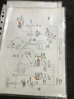
aedc06d8-40a0-467e-b11e-8733e66443bd.jpg
 
Wow, thanks for the detail.


Does the problem boil down to stretching in the material between the main roll and the final nip rolls at 17N041 (I assume this is a few mil of plastic)? Does the "fotocel" at [pos 1] try to eliminate or mimimize the effect of that stretching as source of uncontrolled variation?
 
@drbitboy - No slippage is not an issue on the line currently. I have to make big assumptions at the minute.

We don't get the line until Jan 4th to start the rewire. Looking at it though, that fotocel (sic) may just be the registration mark.

@ Jobbe9000 - I don't know, yet!

My problem is I have to CAM the rotary knife to the linear 'conveyor', which is fine I can do that.

But the knife is a big weight so just doing a cut and stopping and waiting, then doing another won't work, it needs to rotate and sync almost continuously. It should never need updating as once you cut @ 950mm, keep doing so and all should be good, but that doesn't feel right.

We have a safety net as the job was of large nature and we have 5 of these to do, Routeco the RA UK distributor has paid for a Rockwell Tech for 7 days FOC to us. But I would like to figure it out on my own first!
 
This is easy with a RMC75.
https://deltamotion.com/peter/Videos/FlyingShear/SimpleFlyingShear.mp4
Cam tables are not required. Rotational cutting is just a simple modification.
Changing the cut length and phasing can be done on-the-fly.
There is no need for cam table. There is no need to stop the rotation. The motion can be continuous.


drbitboy, this uses the chain rule big time.
Our newer controllers also can use an alpha-beta-gamma filter to smooth out the motion to provide accurate position, velocity and acceleration information for the slave to gear to.


We have a sales engineer in Edinburgh.
 
A few thoughts on this project

First we do not have all the information we should have
But from the limited information you provided
On the drawing you have a drive with a description on MASTER
While the motor speed for the master drive it’s used for the speed reference of both the in feed nips drive and the drum speed reference. But stop and look at the drawing the Nip rolls drive is a torque control drive the speed reference would be just for the upper speed limit in case of a web brake. It would not control the speed. The web speed would be controlled by the out feed nip rolls
The web feed from the torque controlled nip rolls to what they call a dancer. That dancer is more like an accumulator but there should be a tension feedback attached to the dancer most likely a load cell or air regulated dancer position, also because of the high number of dancer rollers I would expect that the web tension would be very light.
The drum roll drive would be a standard drive with just standard feed back no encoder feed back. The load on the drum drive would be fairly constant so the speed would remain constant. And if the web speed remained constant the seal position should remain constant.
The encoder on the drum motor would be to count the pulses after the seal blade trips the prox.
This would give you a starting point for the Ink Jet printer. The ink jet printer would print either a registry mark or a barcode on the bags. (a number of counts from the seal to start printing ) The printer has its own encoder to control the printer all it needs is a contact closer to start the print
It looks like there is a folder of some king after the printer
The out feed nip rolls are operated on a regen drive to control the tension and speed of the web through the drum – printer – folder
Notice there is a registry reader at POS1 the encoder on the out feed nip motor would be to control the position and speed of the Perf drive and again that looks like a regen drive to allow for rapid speed change, and control the perf.
The out feed nip rolls get a reference command from the B&R controller I would assume a 0-10V signal
You notice that the out feed nip drive also gets a signal from a position pot and a 0-10V signal from some other device to set I assume the other device is a tension sensor located on the dancer . these 3 signals would set and control the speed and torque of the out feed nip rolls drive
This same speed reference signal from the B&R control would also be the reference signal to the downstream winder. The downstream winder would have its own controls and I would assume that it would get signals and commands from the B&R controller
In all this is not a real complicated job break it down to each of the components
As for setting the CAM of the knife drum there is really nothing to set the surface speed of the drum must be the same as the web line speed at all times , change the drum size , change the drum speed
( Preset’s) the drum size will give you the distance between seals ( Bag Length)
The fact that they do not have an encoder feedback on the drum tells me that that speed is not critical in this application. In fact from what I see it looks like most of the encoders are used to measure the position , jet printer Dum speed feedback the B&R PLC speed reference to the Perf drive
The Perf is not described very well here but it would require more care to setup it looks like it’s a flying rotary shear. when the shear makes the cut the surface speed of the knife must be travelling at the same speed as the web in order to do the perf at the correct location and without damaging the web. The drive will need to slow down and speed up to cut at the correct location or it could be a simple cam that’s closed at the correct time with the that one of the unknowns here.

If I were going to replace any of the drives in the machine I would not use any servo’s. this project could be done very well using standard vector and flux vector drives at a lot better price in fact they would be a big improvement over the original drives.
I would also use Ethernet drives and get away from most of the analog signals used.
The plc control would have to include operator presets for the different size drums used.

I hope this helps
Good luck with this project let us know how you make out
 
@drbitboy - No slippage is not an issue on the line currently. I have to make big assumptions at the minute.


I was asking about stretch, not slippage.


Because if there is no stretch, then the length of material from the seal to the knife is constant, and since you also know the speed (rotation drum angular velocity (in radian/time) times radius), then there is a direct correlation between where on the material and when the knife needs to make the perforations. And doesn't torque control on 17N041 fix the stretch at a constant value*?


That is just first-order thinking, of course, and I am sure the second order issues are much more involved.


Or maybe I am completely misreading the process: does the [pos 1] [fotocel det... inktjet?]** sense the seal and the knife fire is offset from that event?


* temperature-dependent, perhaps

** are the diagram annotations in Dutch? I cannot quite read them.
 
Originally posted by Peter Nachtwey:

Hopefully the Rockwell controller has a command for this because I don't think cam tables will work if they must be generated and executed on-the-fly.
:

In a Logix controller you would likely use the concept of "pending cams" to address this. You would break your profile up into multiple smaller cams and have their initiation contingent on the status of the previous cam instruction. This allows you to change the cam on the fly but the timing can get a little interesting. This is how I would change between different repeat lengths at the job level but it would work equally well for registration moves. Not as easy as how you can do it in the RMC, Peter, but workable.

Originally posted by Jobbe9000:

You should be able to offset your cut by executing a MAM instruction on top of the MAPC ?

This is how I would do it but not as an offset to the perforator axis. Gear a virtual axis to the web encoder and use that virtual axis as the master axis for the perforator axis. Then apply your offset moves to the virtual axis. Basically you will be advancing and retarding the perforator's picture of the web, which will phase the profile to the web. An MAM into the perforator axis will shift the perforator profile relative to the physical perforator drum, meaning the perforator tip may not be going web speed when it contacts the web.

Keith
 
The light may be starting to come on (or maybe I am just flailing; either way, this may serve the same purpose as Duck Debugging):


At 950mm/bag and 100m/minute I get 570ms/bag =


  • 950mm/bag * 0.001m/mm * 1/(100m/minute) * 60000ms/min

so at an optimistic scan time of 1ms, that is 1/570th of a bag or around 1.6mm resolution, if a PLC were to control this process.


That seems too big, so may I assume that a PLC and/or HMI is the front end for a digital device that is running at a much higher scan rate, or even an analog system? Or does the MAPC instruction drive (interpolate?) a PLC-internal model that has a much higher time resolution?


PeterN: see here for Master Lock Position, perhaps; I'm sure I don't fully get it but I expect you will.
 
The Logix motion system operates much like the SERCOS-based systems (Bosch-Rexroth, etc) where the plc generates a coarse profile and the individual axes interpolate between coarse updates. In addition the motion timeslice in the plc operates as a high priority interrupt so it isn't a affected by the plc scan time...unless you start really jacking with priorities. So while you can't necessarily respond it 1 msec to an external event you can produce a profile that will include a very small correction.

Another point to keep in mind is that the ability to hit any given position is influenced by the controlled axis being able to stay on profile by itself. Said another way, mass is your friend. Counterintuitively maybe, it is easier to keep a flywheel on profile than a loop of spaghetti. So while a controller may not be updating fast enough to detect a 0.1mm position change between scans, that doesn't mean that the controller can't keep the axis following a profile to within 0.1mm.

Keith
 
You seam to forget the length of the bags is fixed ½ of the drum diameter
That’s why he said they change the drum for different bags. If they change the drum they change the bag length. If the diameter of the drum changes then the drum surface speed will change for a given motor speed. So you will need to adjust the drum speed so the drum surface speed matches the web speed.
I am assuming the bag material is a poly material of some type and the seal knifes are actually heated strips in the drum. The requirement here is that both the drum surface speed and the web speed are the same. If they don’t match then the bags will not be formed correctly. In this application a lot of processing power is not necessary and as I said before servo driver are not necessary the original drives were not servos. I have seen similar machines designed and run for many years without a plc at all just analog speed commands
It would be nice to see all the other controls to get a better picture of the overall machine
 
As stated the drum drive needs to change rotational speed based on the installed drum so it makes a bad web speed reference. That is why:

Originally posted by janner_10:

A Lenze Servo controls the Perforator, the proceeding NIP rollers shaft encoder feed straight to the Lenze, which I'm guessing is speed feedback up stream.
bold added

That DOES make for a good web speed reference. Presumably they are not changing the perforator with the seal drum so the perforator axis will need to profile. Also presumably, the operators need to enter the bag repeat somewhere so a base cam can be calculated from that. The only thing the drum really provides is the location of the seal, which the perforator needs to hit. The rest is tracked from the nip roll upstream of the perforator. Depending on how close the nip is the perforator, stretch may or may not be a concern since the true displacement effect of strain is relative to the stressed length.

Keith
 
PeterN: see here for Master Lock Position, perhaps; I'm sure I don't fully get it but I expect you will.
Thanks, it is position where the master position starts indexing to the cam table and the slave is locked or geared to the master.


There are coarse updated and fine updates on a Rockwell controller. The fine updates are 250 micro seconds on a M02AE, HYD02 or M02AS. ( motion modules ) They fine updates can be shorter on the newer drive type controllers. I don't know anything about them.


If the drum size changes to match the cut length then this should be easy and cam tables are not required.


HOWEVER! From janner_10's first post.

janner_10 said:
My problem is to CAM the knife to the proceeding nip rollers speed with the registration mark of the seal position, this I can do however, I would like to dynamically change the cut position or master lock position every cut, the bag length won't ever change mid-cycle but without this there is no checks or balances IMO, this is the part I am having trouble with.

I doubt drums can be changed on-the-fly.
The lock position is basically the offset I was talking about.
 

Similar Topics

Hey everyone. Im doing rotary knife application for my senior design project. I need some help about the program. i dont understand some parts...
Replies
0
Views
1,848
Dear sir I have one rotary knife for paper. This machine has one DC motor and DC drive for cutting web. I want control cutter with PLC . Please...
Replies
33
Views
12,082
Hi.. I have flying shear application using rotary knife. The line speed is 100 FPM and rotary knife using Vector motor with Inverter for speed...
Replies
5
Views
6,454
Hi All, I have a rotary cut-to-length knife application and I am using an AB 1394 drive. Board Speed range 40 to 90fpm. Cut length 8 to 16ft. A...
Replies
15
Views
9,449
M
I,m looking for a controller for a rotary knife, similar to the contrex m-rotary, but with better interfacing capability(such as modbus). The...
Replies
1
Views
4,337
Back
Top Bottom