Plc controlling traffic lights

Anastasis

Member
Join Date
Feb 2021
Location
Thessaloniki
Posts
8
Hello everyone... I am new to the PLC world and I would really love it if you gave me some interest about the problem I am dealing with for about 1-2 weeks. It's about a paper I have to deliver for school until the 12 of the month.
I am doing a traffic light controller using plc especially STL programming.


I want to make a cycle of 2 traffic lights one for the vehicles and the other for (you guessed it right) the pedestrian.
I will need one button (saying I0.1 ..) only for the sequence to begin(NOT a pedestrian button as I saw many times on the internet about other papers..)


Firstly, I want my green light for the cars and red light for the peds to be turned on even thoug I have not pressed the button.
The sequence i like to do ONLY WHEN I PRESS THE BUTTON is the following:
1) GR_CAR & RED_PED = 15s
2) YEL_CAR & RED_PED = 5s
3) RED_CAR & GR_PED = 4s
4) RED_CAR & RED_PED = 3s
5) AND IN THE END I WANT TO HAVE GR_CAR & RED_PED AGAIN BUT THIS TIME FOR 10 seconds.
This is my cycle and i want that to happen all over again when it ends (as you can imagine).
Pleaseeee If you have something in mind let me know with a response cause i really need some help over here....
Try not to laugh too much at me I am new...
Thanks in advance!!
 
Network 1
LD I0.1
S M5.1,1
Network 2
LD M5.1
TON T33,300
A T33
S M0.0,1
Network 3
LDN I0.1
S M5.5,1
S M5.6,1
Network 4
LD M5.5
= Q0.0
Network 5
LD M5.6
= Q0.4

Network 6
LD M0.0
AN T39
= M0.0
Network 7
LDN M0.0
= Q0.0

Network 8
LD M0.0
TON T37, 50
Network 9
LD M0.0
LDN T37
O T39
ALD
= Q0.1
Network 10
LD M0.0
A T37
= Q0.2
Network 11
LD Q0.2
TON T38, 40
Network 12
LD Q0.2
AN T38
= Q0.3
Network 13
LD M0.0
A T38
TON T39, 30
Network 14
LD M0.0
LDN T37
O T38
ALD
ON M0.0
= Q0.4

END


What i am dealing with is this:


1) It does not cycle... cause when the last energy is done it doesnt have the right time in the first energy( GR_CAR & RED_PED ) whitch is 10 seconds...


2)I cant have the GR_CAR & RED_PED in the end of the sequence energized for the time i want...


I am sorry that I did not post that but it is not working as it should so I guessed it is not usefull..
 
Also the timings are different here...
I am sorry that i am using STL but it's about the purposes of the paper...


Concluding I am doing that in a simulation (Microwin 7) and I can have the sequence of 1,2,3,4 but i cant have the GR_CAR & RED_PED turned on for the time needed in the end (meaning after RED_CAR & RED_PED) and the other problem I am dealing with is that when it starts all over again the cycle it goes at the first activity( GR_CAR & RED_PED ) only for some milliseconds saying and NOT for the time I want which is (10 seconds).
 
Network 1
LD I0.1
S M5.1,1
Network 2
LD M5.1
TON T33,300
A T33
S M0.0,1
Network 3
LDN I0.1
S M5.5,1
S M5.6,1
Network 4
LD M5.5
= Q0.0
Network 5
LD M5.6
= Q0.4

Network 6
LD M0.0
AN T39
= M0.0
Network 7
LDN M0.0
= Q0.0

Network 8
LD M0.0
TON T37, 50
Network 9
LD M0.0
LDN T37
O T39
ALD
= Q0.1
Network 10
LD M0.0
A T37
= Q0.2
Network 11
LD Q0.2
TON T38, 40
Network 12
LD Q0.2
AN T38
= Q0.3
Network 13
LD M0.0
A T38
TON T39, 30
Network 14
LD M0.0
LDN T37
O T38
ALD
ON M0.0
= Q0.4

END


What i am dealing with is this:


1) It does not cycle... cause when the last energy is done it doesnt have the right time in the first energy( GR_CAR & RED_PED ) which is 10 seconds...


2)I cant have the GR_CAR & RED_PED in the end of the sequence energized for the time i want...


I am sorry that I did not post that but it is not working as it should so I guessed it is not usefull..


I am not looking for anybody to do my homework though I would really apreciate some help over here
I want to do it in STL language or LADDER logic.
 
Most people on here can do STL but its a lot easier and you will get more help if you post your work in ladder and explain the issues you are having
 
Probably is best if you use a sequence word rather than setting/reseting bits.
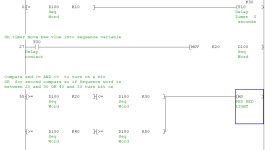
You have your sequence so try this idea

Start button moves a 10 into a memory (what ever it is a FW, Data word etc.
Then do a compare for 10 to start a timer for the first stage of the sequence.
When timer up move 20 into the word
again do the compare and a timer, step on.
Keep doing this for each sequence
at the last sequence move a 10 (or 20) into the sequence word to go back
Note: as you require an initial 10 seconds from start button (car) next time round you need 15. that's why a jump back but not to the start seq.

Then use the compares to enable the red/green lights
I suggest you write down the number of sequences (use a base of 10) this is because it is easier to add extra steps in between is required.
Here is a two way traffic but not STL or Siemens and only an idea so don't think I'm doing the code for you just an idea, I have used sequential numbers 1,2,3,4 etc. but I suggest using steps of 10 as easy to add extra steps without moving everything.
 
Never used the S7 200 but providing you have Compare instructions i.e.
CMP >, <, = >=, etc. there is no reason why not
The timers I'm using are IEC timers but all they are standard delay on timers
The logic symbols for the AND & OR may be different this was done in FBD which I think are available in S7 200, however that is a guess.
The SEQ. Variable could be a Data block word or a Mword (MW). Or I think the 200 has V memory.
So for compares (STL in the old S5)
L MW200 // My Sequence variable
L KF +10 // number to compare to
!=F // if equal
= M10.0 // then turn on M10.0

STL for Timer equivalent
L MW200 // My Sequence variable
L KF +10 // number to compare to
!=F // if equal
SD T20 // start timer (this may be TON T10)
A T20 // timer up
L KF 20 // load sequence number
T MW200 // transfer to the sequence word
I suggest you try to do it in FBD or ladder.
Here is a snippet in ladder may differ for S7 200

ladder.png
 
For any given homework assignment or task at work, you must consider these instructions as the customers specifications.
1. read the specifications several times.
2. write down your understanding of what you read in a step by step fashion.
3. review what you wrote down and see if it makes since, modify if necessary.
4. Get with the mechanical designer and discuss the project openly and honestly. When your opinions differ in regards to an operation, discuss it, don't ignore it.
there must be a reason for a difference of opinion. modify your instructions and i/o to accomodate the mechanical design if necessary.
YOU BOTH MUST be in agreement on all points of operation before going to step 4.
5. step through your notes again this time, you are the one following the instructions. In other words, you are the plc. Write down on paper the events you are doing.
For example, turn on hydraulic motor 1, write down hydraulic motor 1 on. If a sensor is needed, write that down.
6. continue through the instructions. When you turn off the motor, mark a line thru it.
7. go through your instructions with all the sensors, motor aux. contacts, outputs documented. Modify if necessary.
8. repeat step 6 until no changes are made.
9. Try to group your data words into some organized fashion. The more programs you write, the more organized you become
10. write the plc program using your notes in a step by step manner.
10A Over half way through writing the program you WILL realize a different/better way of doing something you are almost done writing
(or a new spec will require it) and you will completely rewrite it
10B It WILL happen more than once.
Note: 10A and 10B aded to list. thanks Aabeck, member plcs.net forum

11. DOCUMENT EVERYTHING!!! You may remember things today, but in 5 years and hundreds of programs later, you won't
remember, especially at 2 am, so DOCUMENT EVERYTHING. use easy to understand tags and rung comments.
12. MAINTENANCE is your best friend and your worst enemy.
if you work with them and find out what they can do, write the program where they can trouble shoot the program. they will be able to fix the problem and everyone will be happy.
BUT
if you write the program to where you are the only one who understands what is going on, maintenance can't fix the issue, the machine is down, production is down,
management hears about it, your boss hears about it, then you hear about it - rewrite the program or else. you get calls all hours of the day and night.
this still holds true, a machine can cost a billion dollars, but it's not worth 10 cents if maintenance cannot trouble shoot the issue and fix the issue.
everyone has their own style of programming and you must develop your own way as well.

13. when the customer is in your shop and brings maintenance, discuss thngs with them, let them see your code, be open.
if they make suggestions, write them down, don't ignore them. their ideas may save you days of programming.

14. install the program and leave in program mode if possible so you can to debug your i/o
15. when writing your instruction manual(s), use your notes from step 9. Use easy to understand English language. specify the i/o, timers, counters, outputs when possible.
this will help maintenance even more to see what is going on.
16. Question for you, when is a machine and plc the most dangerous and why?
When it’s first powered on – when power is first applied to a machine, you don’t know how things are wired.
When you energize the plc outputs, you don’t know how they are wired.
When the plc is put into run mode the first time, it will do what you told it to do, NOT what you wanted it to do.
17. debug the program.
Remember, the program will always do what you told it to do, NOT what you wanted it to do.
18. IF you can ask a what if this happens type of question, YOU MUST have an answer, EVEN IF its a 1 in a million change.
that what if situation will happen in the first 30 minutes of production runoff in front of the customer.

this is the best advice I can give anyone.
if others has more / better suggestions, feel free to post
James
 

Similar Topics

Hi All, I am facing one issue with the SEW MDX61B drive. Issue- I want to run a conveyor with this drive in two directions but it runs in...
Replies
0
Views
329
Hello. I am using the following: Eaton E4-AC-12RXP PLC I am trying to control the CL86T which controls a Closed-Loop Stepper motor. I am using...
Replies
3
Views
958
Hi all, I'm new to this forum and really new to the world of PLCs. This may seem like a really dumb question but is it possible for a HMI to...
Replies
6
Views
1,768
Urgent Help needed I have to migrate a S7 300 PLC system controlling a plant which is currently in operation, from SIMATIC NET V6.3 to V.15...
Replies
0
Views
1,333
Hello sir, I am using Allen Bradley Micrologix 1200 PLC and Pannel view plus 600. I have written my ladder logic and verified...
Replies
1
Views
1,534
Back
Top Bottom