Analogue scaling

john clay

Member
Join Date
Jun 2003
Posts
6
I have been given the task of scaling two analogue outputs to drive two conveyors.The setpoints are set in the scada system. The first analogue output will be the master from the set point, the second analogue out will be slaved and has got to be scaled slower than the first. I am obviously writing the analogue outputs to two inverters, I cannot use the fist set point as a master and then slave the second on the inverters, it has to be done by two outputs from the plc. The plc is Allan Bradley SLC 505 and the Skada is RS View. This is my first ever question, I hope someone can understand it and will reply!!
 
need a little more info ...

Question: Is the SLAVE a percentage of the MASTER (example: SLAVE = MASTER * 0.95) .... or is the SLAVE simply offset from the MASTER (example: SLAVE = MASTER - 123) .... or is there some other arrangement?

Question: Do you already know the minimum and maximum values which will be sent to the MASTER and to the SLAVE?

This information would help us give you a more specific answer.

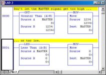
Regardless of how you accomplish your task ...

[attachment]

This little "limit-a-value-to-a-specified-range" programming technique comes in very handy in many situations. Use of this arrangement both for the master and for the slave is highly recommended. This can help prevent the operator from cranking in too high or too low a number - and help prevent math "round off" errors from generating an invalid signal to the inverters.

Specific CAUTION: Contrary to what many programmers assume, the handy little SCP instruction does NOT limit its output between the minimum and the maximum values that you enter. I'll mention that here because the SCP just MIGHT figure into your final solution.

not too high not too low.jpg
 
Have not used RS View but you should be able to set up a write command to the PLC from the SCADA for the first output and then subtract a value in the PLC for the second value to write to the analogue outputs. I have regularly done this type of thing in Citect by using "thumbwheels" to increment and decrement channels on a rising edge trigger. The value is returned to the SCADA screen so that the operator can see the value changing. When the operator is satisfied with the value, press a "set" button on the SCADA screen which will then write the value into the real channel that you wish to use to drive the analogue output.
beerchug
 
Many thanks for the reply.

I think what I will be doing is offestting the slave from the master. I do not know yet the minimum and maximum values but they will be set so that the operator only has a narrow parameter to set the speeds once we have determined the speeds for the products.

My own thoughts are scaling from the skarda of 0-50 which represents a frequecy, scaling it with parameters to write to a 0-10 volt analogue out. I also thought of using parameters equal to and then copying the second speed to the second output is slightly less - we will have to monitor this when it is complete to get the correct speed for the product.

I would welcome your thoughts.

John
 
maybe this will help get you started ...

John,

if I understand what you’re asking ... here are the basic ideas based on what you’ve posted so far ...

have the SCADA operator input a value between 0 and 50 into a tag (such as: HZ_INPUT) example: operator inputs “47”

have the SCADA transfer the value of HZ_INPUT into an integer in the SLC (such as: N7:0) - document N7:0 as “master hz input” - example: N7:0 now contains “47”

use an SUB (Subtract) to offset the slave’s frequency from the master’s frequency (example: N7:0 ... minus 2 ... to destination N7:1) - document N7:1 as “slave hz input” - example: N7:1 now contains “45”

USE THE LIMITING CODE which I posted above to make sure that the values for BOTH the master and the slave do not get out of range - specific example: suppose that the operator enters “0” as the input value - then without the limiting operation, the slave would contain the value “-2” ... now what would a “-2” speed signal do to the slave? ... we don’t know ... we don’t want to know ... so make sure that only valid speed signals get posted to the inverters ....

use an SCP (Scale with Parameters) to scale the “master hz input” value from N7:0 and place it in the proper output location (such as: O:1.0) which serves as the master inverter speed signal (example: assuming that your output card uses values of 0 to 32767 to give an output signal of 0 to 10 volts, then O:1.0 will now contain the value 30801 ... and the master inverter should see a “speed control” input signal of 9.40 volts)

use an SCP (Scale with Parameters) to scale the “slave hz input” value from N7:1 and place it in the proper output location (such as: O:1.1) which serves as the slave inverter speed signal (example: assuming that your output card uses values of 0 to 32767 to give an output signal of 0 to 10 volts, then O:1.1 will now contain the value 29490 ... and the slave inverter should see a “speed control” input signal of 9.00 volts)

again - if I understand what you’re asking for, this approach should take care of your “slave-runs-at-a-slower-speed-which-is-offset-from-the-master” problem

final thoughts - if you work with integer values, then your operator will be able to enter the desired frequency as whole numbers - specifically, “45” would be an acceptable entry - but “45.3” would not be allowed - is this an acceptable level of control (resolution) for your application? - if not, then floating point locations (such as: F8:0) would be in order ...

final suggestion: nail down the actual input and output values that you need BEFORE you start writing the code ... it’s hard to hit a target if you’re not sure exactly what you’re aiming for ...

final question: Do you understand “math overflow” faults? - if not, then I’d suggest that you study up on these. For a specific potential trouble spot: without the limiting feature which I posted earlier (or some other such suitable limiting mechanism) then an operator’s entry of say “55” could fault the processor and shut everything down.

if the solution offered above doesn’t look “just right” then please post again with more specific details -
 
When setting up, you may find that the subtraction value from the input figure to the secondary output figure will vary, depending on the master speed value. If so, you can set up a table or series of compares using => and =<. If the value complies with the compare, insert a different value. This is very easy to set up, and provided your PLC has enough memory, can be an indefinate series of numbers.
Setting up maximum and minimum figures should be relatively easy. Using a SCADA system, it is very easy to set up "thumb wheels" on the screen to add and sutract from an existing figure. If your PLC has @INC and @Dec commands, (increment on a rising edge and decrement on a rising edge from your SCADA thumb wheels), use a compare and when a decrementing number is =< a value, turn on a bit to disable the decrement input line. Similarly, use a compare and when an incrementing number is => a value, turn on a bit to disable the increment input line. You can also return the value to a digital readout in the SCADA system so that the operator can see what the value is and immediately see the result of each mouse press on the value in the PLC. I have used this before and it is fool proof. I use it commonly for adjusting values for timers. You can set up a thumb wheel + and - button for each digit. The compare numbers are also very easy to change on the fly in the PLC when you are commissioning.
If your PLC does not support rising edge increment and decrement, you can use the input from the SCADA into a rising edge trigger internal relay and then use that relay into the increment and decrement command input lines.
I know Omron supports differentiated functions but not sure about AB.
beerchug
 
Last edited:

Similar Topics

Hi, I have a ControlLogix system with 1756-IF16 analogue inputs. I can't scale the inputs at the card as there is a requirement to facilitate...
Replies
3
Views
81
Hello guys I am just wondering do I need to set up each channel configuration, including enabling the channel , ranging … if I have already...
Replies
8
Views
2,012
There have been a number of posts asking about scaling so I thought this may help. The formula is: Out := ((Variable_In - ZeroIn) / (SpanIn -...
Replies
11
Views
6,416
Hi, I have an application with a load cell where I need to log the load cell output, into a small/internal data logger. But I also want the...
Replies
3
Views
1,718
Hello there I am having trouble scaling my analogue input signals. If I use engineering units and use the RAW scale as 4000-20000 everything is...
Replies
10
Views
2,612
Back
Top Bottom