Msg Instruction in RsLogix 500

Dani610

Member
Join Date
May 2018
Location
Adelaide
Posts
33
Hi All, I am new to plc programming. I have created a ladder logic in rslogix 500. Now I want to give input at one plc and get the output on the other plc.
I am using two Micrologix 1400 connected with Ethernet cable. I know that I have to use the msg instruction but i don't know how to use this.

thank you
 
Welcome to the forum.

Question, is this homework or actual work project?

this will have several parts.

1. copy the inputs to a file that can be used in the msg instruction.
2. set up a heartbeat signal between each plc.
3. write the message instruction between each plc.
4. copy the file to the outputs.

the connection between the plc's must go through a switch or use a cross over cable. a regular cable will not work that I am aware of.

download the instruction manual and read up on the message instruction.

I am not the best to answer the message instruction.

show your work and we will offer suggestions.
james
 
Thanks for your reply.
as i told that i am new to plc so
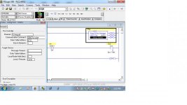
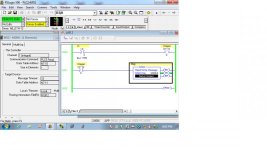
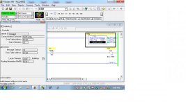
i am trying to do the simple function for now just to understand the msg instruction then i can do the changing accordingly. attached are the screenshots.
in the first plc msg setup screen i have given the address of 2nd plc in multihop tab

Untitled.jpg Untitled2.jpg
 
You might want to get into the habit of assigning 'N' registers as the source and targets of reads and writes in messages. At the 'input' PLC use simple rungs to copy the desired input states into a N register (I:0/0 -> N7:10/0 for example). Let's say the N register on the receiving PLC is N7:11. The MSG command would then send N7:10 to N7:11. The 'output' PLC could then simply copy N7:11/0 to O:0/0.

So to repeat the input PLC copies actual inputs to the N register. The message command transfers the data to an N register in the output PLC. The logic in the output PLC transfers the N register bit to an actual output.

Information can travel the other way also. I found it least confusing to establishing one PLC as the 'leader', doing all the reads and writes. You can decide for yourself.

As suggested it would be best to setup handshaking. That way the output PLC can decide if the data in it's Not register is 'current' as it may want to shut off outputs if communication is broken. We'll let you work on that on your own first.
 
Last edited:
You might want to get into the habit of assigning 'N' registers as the source and targets of reads and writes in messages. At the 'input' PLC use simple rungs to copy the desired input states into a N register (I:0/0 -> N7:10/0 for example). Let's say the N register on the receiving PLC is N7:11. The MSG command would then send N7:10 to N7:11. The 'output' PLC could then simply copy N7:11/0 to O:0/0.

So to repeat the input PLC copies actual inputs to the N register. The message command transfers the data to an N register in the output PLC. The logic in the output PLC transfers the N register bit to an actual output.

Information can travel the other way also. I found it least confusing to establishing one PLC as the 'leader', doing all the reads and writes. You can decide for yourself.

As suggested it would be best to setup handshaking. That way the output PLC can decide if the data in it's Not register is 'current' as it may want to shut off outputs if communication is broken. We'll let you work on that on your own first.


thanks
so i have saved the input and output in the integer file. i was wondering that i will put the same integers into the "data table address' of this controller and target device in msg setup screen.
 
Welcome to the forum.

Question, is this homework or actual work project?

this will have several parts.

1. copy the inputs to a file that can be used in the msg instruction.
2. set up a heartbeat signal between each plc.
3. write the message instruction between each plc.
4. copy the file to the outputs.

the connection between the plc's must go through a switch or use a cross over cable. a regular cable will not work that I am aware of.

download the instruction manual and read up on the message instruction.

I am not the best to answer the message instruction.

show your work and we will offer suggestions.
james

this is a actual work project i have just started in a company and they have given me this. i tried to get something online how to do msg command in rslogix but couldn't find anything that explains the process
 
The error message for your Write message indicates that you've entered an invalid IP address for the target. Check that carefully; every Routing Table entry (the Multi-Hop tab) can be unique.

Also: in general, you'll want to use the "SLC-500 Typed Read" and "SLC-500 Typed Write" commands when transferring data between MicroLogix controllers. The MicroLogix are very similar to the SLC-500 operating system, more so than the PLC-5 operating system.

I have entered the ip address of output plc in target device but not sure about the screen setup bar for write msg block.
 
On your read side your MSG has an error bit set that means there is something wrong and message probably did not came through.

Also I would not use a MSG.DN bit to fire outputs. Your message is being stored in N7 register so I would rather use that.
 
I know, aside the tags, it's practically the same.

Actually, not to be “nitpicky” but for someone who’s new to ladder logic I wouldn’t use RSLogix 5000 (or Studio 5000) as an example of how to use RSLogix 500. Yes they are similar but I wouldn’t say “practically the same”. I think the differences can cause more confusion than the similarities can help but that’s just my two cents.
 
I really appreciate for your feedback. is it possible that anybody can just share a picture of simple message read and write ladder logic is rslogix 500 including the pic of screen setup. i'd be able to learn in that way by then playing around with things.
 

Similar Topics

Hi All, this forum has been of a great help for me in learning. i have two problems 1- I have setup an alarm so i want to calculate the number...
Replies
4
Views
2,933
Hey all, I’m looking to set up a client/server Ethernet connection with a device to communicate to my Schneider plc. I’ve done this before with AB...
Replies
3
Views
2,691
This tripped me up yesterday, thought I'd share the results of a conference call with RA this morning: There is a change between version 10 and...
Replies
3
Views
3,106
I am new to using the rslogix 500 msg instruction, I am getting problems setting it up. I have two a slc 5/03,s connected to ethernet via 1761-...
Replies
13
Views
13,136
I am trying to read/write some INTs between two controllers. They are both set up in an array. I have my MSG configured as a CIP Data Table...
Replies
2
Views
2,614
Back
Top Bottom