RS485 Comms to M340

bilk

Member
Join Date
Aug 2022
Location
Edmonton
Posts
3
Hey,

Long time reader but first time poster here! I need some input/advice with the following problem:

I need to write code for M340 that will read CO2 and Temperature from a sensor with model Si-QS5R3A0.

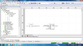
Please see attached a tell me what I'm missing here...

Sensor is slave addy 1, 9600 8bits, 1stop, no parity. Reading 4x registers between 2dec and 47dec. Getting blinking light on CPU, no errors in management table, but no info coming back from the sensor.

485Test1.jpg 485Test2.jpg 485Test3.jpg 485Test4.jpg 485Test5.jpg
 
Last edited:
Welcome to forum.


There is several possibilities.
You should only send one modbus query at time to serial side.
Now when you have bit directly to EN input and without rising edge detection and also without management table's activity bit result is that block is sendind several modbus querys and serial traffic jams.

(Activity bit is LSB bit of 1st managament word)

Also timeout parameter should have different value than 0.
Value 0 means infinity timeout for block and block cannot send new modbus querys as modbus query before haven't timeouted. (software timeout)


On card settings is retries 3 and timeout 100*10ms (default). This means that one modbus query is listened at least 4s before so called hardwire timeout. You can set retries to 0 and 3rd managemet paramter to 20 or 50 (=2..5s), then software and hardwire timeouts don't break traffic.


But biggest problem probably is that CPU's serial RS485 communication needs biasing to RS485 side.

If you would have NOM0200 card on M340 then card have inbuild biasing.
But for M340 CPU you need seperate biasing connection. Scheider have device called TWDXCAISO for biasing RS485 and isolation.
 
Last edited:
Modbus addresses 2dec to 47dec are 46 16-bit INTs, so RECEIVE tag should be ARRAY[0..45] OF INT, not [0..44], which is only 45 INTs.
 
Thanks guys for the quick responses.

LARE,

I just toggle that enable bit manually for now, but yes I will add rising edge detection for sure.

My intentions were to use that 3rd position on the manager rather than the card default values. Being 9600 baud, its pretty slow so I set to 100 (10seconds) - %MW102. See 485test2. Did I put in the wrong place? Its array 0..3

I think you nailed it with the bias resistor/cap. Will try this asap.

DRBITBOY

Yes, fixed this. Old school math, my bad!


3rd paremeter is right.
RS-ports have own processor, that is why there is own timeout value on card setting. It is called to hardware timeout (485Test1.jpg)
Hardwire timeout is now original query and 3*retries if no reply from slave.

This means that on communication error you should wait on PLC side at least 4s before sending new message.

(Communication processor sends 4 (original + 3 retries) messages if slave don't reply.)


(Your variable Manager[0].0 is activity bit now. It tells if querys is still active. Send new message only after this bit is goed to false.)

You should see that this activity bit is true for 4s as you don't get reply, after that time it goes to false.


If you adjust software timeout to less than hardware timeout, this leads to that management parameters activity bit is reseted, but communication processor is still waiting reply from slave.

If you now send new query to RS-port. New query is not sended at all or there is collisions on RS-side and you get communication errors.


If you adjust hardware retries to 0 you can send new modbus messages faster if there is multiple slave as timeouting one slave's message takes less time.


10s is more than ok now, even 5s would suit.


You can test reading whit only one address.

Then look PLC RS-port TX led and slave's rx led if there is any. Both should blink.

Afte you get succesful message for one variable change query lenght to 46.


Of course you have swapped allready A and B wires and have 120 ohm resistors on both sides if RS-wiring is long. (y)


If both master and slave leds blink but you get error, change A and B wires. If still no reply and communication settings and slave address is right then it is probably biasing.


p.s TCP communication is allmost same. Only 0.0.0.1 address needs different addressing. If your slave have also TCP port you can test communication without XCA ISO.

 
Last edited:
Modbus addresses 2dec to 47dec are 46 16-bit INTs, so RECEIVE tag should be ARRAY[0..45] OF INT, not [0..44], which is only 45 INTs.


True.

Read_var's RECP buffer can be longer than readed words from slave.

But if readed words from slave is longer than RECP buffer on master communication don't work at all.
 

Similar Topics

Hello, Not an expert at all in comms need some help trying to figure something out. I have a plc and hmi that i am trying to establish rs485...
Replies
10
Views
3,130
Hi guys Just wondering if anyone has succesfully read barcode data from these barcode scanners to a plc via rs232 or rs485? If so do you guys have...
Replies
0
Views
1,461
hello everybody, i am wondering if anyone can help me with a little problem im having, i have a standard (4/5 wire) usb to RS485 adapter, and i...
Replies
0
Views
1,772
Can anyone shed light on this: I have an RS485 Modbus setup currently with an ML1100 and a Multitek DMM, 8E1. 8N1 will not work, because the...
Replies
1
Views
2,234
Got a small project that involves several mitsubishi FX1N talking to a FX2n. Comms is done via the RS485 card attached to the FX's. Problem is...
Replies
4
Views
2,642
Back
Top Bottom