![]() ![]() ![]() ![]() ![]() ![]() |
||
![]() |
||
![]() ![]() ![]() ![]() This board is for PLC Related Q&A ONLY. Please DON'T use it for advertising, etc. |
||
![]() |
|
![]() |
|
Thread Tools | Display Modes |
![]() |
#196 |
Lifetime Supporting Member
|
Another typo at Subroutine 50 Test Pressure, Rung 5: high/low tolerance tests are reversed?
__________________
_ Brian T. Carcich i) Take care of the bits, and the bytes will take care of themselves. ii) There is no software problem that cannot be solved with another layer of indirection. iii) Measurement is hard. iv) I solemnly swear that I am up to no good ![]() v) I probably have the highest ratio of forum posts to actual applications in the field (∞). vi) Hakuna matata. |
![]() |
![]() |
#197 |
Lifetime Supporting Member
|
Subroutine 30 Discrete Valves, Rung 2, Compare of DS1 Sequence Step to 60 (Test Pressure Hold) should be <, not ≤, because the pump should not be available to restore the test part pressure if it drops.
By the same reasoning, in Subroutine 99 Outmap, Rungs 6 and 7 should write 0.0 to the I/P transducer during step 60, the ≤ 60 on Rung 6 should be < 60, and the > 60 on Rung 7 should be ≥ 60.
__________________
_ Brian T. Carcich i) Take care of the bits, and the bytes will take care of themselves. ii) There is no software problem that cannot be solved with another layer of indirection. iii) Measurement is hard. iv) I solemnly swear that I am up to no good ![]() v) I probably have the highest ratio of forum posts to actual applications in the field (∞). vi) Hakuna matata. |
![]() |
![]() |
#198 |
Member
|
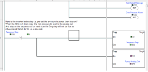
Regarding slowly increasing the pressure the pump will not run at probably 6-7 ma (assume 10 psi, so I suggest when you start the pump on a oneshot (perhaps an extra step you have plenty spare as it appears that all posts so far are keeping the steps of 10) for example if step 10 was to start the pump, from 0 (Idle) move 5 or what ever into the sequence step number, move say 7 ma (min pump start air pressure) then move 10 into the seq register this in itself is a oneshot so then you have a starting air pressure rather than starting at 0 & the pump will not run until the I/P (Current to pressure) (yes that is what it is called not a transducer that is ambiguous as it also refers to a signal back (analog input)rather than analog output).
See pic on extra step to pre-load (you may have to change the step number to fit in what others or you have done). |
![]() |
![]() |
#199 |
Lifetime Supporting Member
|
Another bug in Subroutine 20 States, I think; see the attached image.
Untitled.pngWhat started me thinking about this is, after the NO Contact C2 HMI_PB_Cycle_Stop on Rung 3, the NC Contact C2 HMI_PB_Cycle_Stop on Rung 4, which is not necessary:
So maybe that is supposed to be C1 in Rung 3? P.S. I assume each of those bits is "active" (i.e. to start or to stop) when its value is 1. Or maybe this is what was intended: pressing HMI Stop transitions to State 10 (Idle) from any state; pressing HMI Stopm, while both (i) in State Idle AND (ii) test part is depressured, transitions to State 20 Ready. Untitled2.png
__________________
_ Brian T. Carcich i) Take care of the bits, and the bytes will take care of themselves. ii) There is no software problem that cannot be solved with another layer of indirection. iii) Measurement is hard. iv) I solemnly swear that I am up to no good ![]() v) I probably have the highest ratio of forum posts to actual applications in the field (∞). vi) Hakuna matata. |
![]() |
![]() |
#200 |
Lifetime Supporting Member
|
This might work. I wonder if there is a conversion app from Click to DoMore; this should be straightforward to simulate.
[Edited: fixed a typo in the program]
__________________
_ Brian T. Carcich i) Take care of the bits, and the bytes will take care of themselves. ii) There is no software problem that cannot be solved with another layer of indirection. iii) Measurement is hard. iv) I solemnly swear that I am up to no good ![]() v) I probably have the highest ratio of forum posts to actual applications in the field (∞). vi) Hakuna matata. Last edited by drbitboy; January 24th, 2023 at 04:52 PM. |
![]() |
![]() |
#201 |
Lifetime Supporting Member
|
Here are some of the key pieces of the algorithm that sets the air pressure regulator setpoint. At its core it does summat similar to what the human operator seems to be doing:
__________________
_ Brian T. Carcich i) Take care of the bits, and the bytes will take care of themselves. ii) There is no software problem that cannot be solved with another layer of indirection. iii) Measurement is hard. iv) I solemnly swear that I am up to no good ![]() v) I probably have the highest ratio of forum posts to actual applications in the field (∞). vi) Hakuna matata. |
![]() |
![]() |
#202 | |
Lifetime Supporting Member
|
Update: I forgot to attach the image to that last post; here it is below.
Quote:
Untitled.png
__________________
_ Brian T. Carcich i) Take care of the bits, and the bytes will take care of themselves. ii) There is no software problem that cannot be solved with another layer of indirection. iii) Measurement is hard. iv) I solemnly swear that I am up to no good ![]() v) I probably have the highest ratio of forum posts to actual applications in the field (∞). vi) Hakuna matata. |
|
![]() |
![]() |
#203 |
Member
![]() ![]() Join Date: Jan 2023
Location: Louisville, Ky
Posts: 66
|
Hello all. I have been making the program that @drbitboy made into do more designer and also edited some things. Before I try to finish up the simulation I need to understand what things I really need for this whole system to work.
I redid my diagram for what parts I need and other things. Here is the diagram. https://imgur.com/a/XpzsHdk The pressure regulator we are using now has a filter in it so I will put that at the beginning of the system, it can also act as a safety valve just in case the pump air shutoff valve does not work. Before an operator starts their day testing parts all they need to do is fully open the regulator knob. Also added the shutoff valve right after it because the I/p transducer cannot fully stop the pump from running, it can only go down to 3psig. When the shutoff valve is closed during pressure testing, there will be pressure still between the shutoff valve and the pump which will hold the systems pressure. When the test is done simply all we need to do is send a signal to open this valve and the output pressure in the pump will go to zero and the test is ready to go again. Let me know If this all looks okay because soon, I will simulate the pump and the devices. I am not 100% sure if the 2-way pneumatic solenoid valve I picked can withstand a difference of 120psig on one side and 0psig on the other. It says on the website that its maximum operating pressure is 180psig so I think this valve will be fine. Here is the link to it. https://www.grainger.com/product/RED...-in-Pipe-6WTP5 I still need to find a pneumatic solenoid relief valve for part D, I can't find one that is solenoid controlled and can withstand a pressure of at least 1500psi. I want to be able to open this pneumatic solenoid relief valve at any pressure. I also still need to find a mechanical water pressure relief valve that's setpoint is 1500psi. Last edited by Aljubovic; January 31st, 2023 at 03:23 PM. |
![]() |
![]() |
#204 |
Lifetime Supporting Member
|
Sounds great.
I don't see how solenoid relief valve D can reduce pressure on the water discharge side of the pump, because the pump has check valves on the water side. Also, valve D should never see more than 120psig.
__________________
_ Brian T. Carcich i) Take care of the bits, and the bytes will take care of themselves. ii) There is no software problem that cannot be solved with another layer of indirection. iii) Measurement is hard. iv) I solemnly swear that I am up to no good ![]() v) I probably have the highest ratio of forum posts to actual applications in the field (∞). vi) Hakuna matata. |
![]() |
![]() |
#205 |
Member
![]() ![]() Join Date: Jan 2023
Location: Louisville, Ky
Posts: 66
|
How would I reduce pressure in the whole system then? Would I also need to put a solenoid valve on the water side or is their one solution to depressurize the whole system?
|
![]() |
![]() |
#206 |
Member
|
You should't need too, the water is dumped by G (but you have that as a manual dump, B will shut off air to the I/P so assume the following:
G (Water dump) should be open to drain, blocked to water from pump when de-energised So this should be an automated valve n/o tp drain. This closes at the start of process i.e. energised throughout the test. When pressure is required for the pump to run (regardless of if it is low i.e. 4ma or 20ma) then open Valve B, modulate the air as required by the I/P, when target pressure reached shut of Valve B. at the end of the test open valve G. I have no idea why you have the pressure relief valve if the pump can take max supply air pressure there is no need (if it is a relief in the sense you energise it as thre pump expells air everytime it pumps) if the valve B is closed the air to the I/P will be released by the pump (at least after one cycle) if you sequence was for example: 10 (pressurise system) 20 ( Up to pressure run test time ) 30 (release pressure) 40 (end of test) so Valve B will open between 10 & 20 (Energised) Valve G will close between 10 & 30 (Energised) YOU REALLY NEED AN AUTOMATED VALVE FOR G What could be simpler. Last edited by parky; February 1st, 2023 at 08:37 AM. |
![]() |
![]() |
#207 |
Lifetime Supporting Member
|
The first image below is one example of what a typical, manually-operated hydrostatic test setup would look like, with the #13 unloading (water dump) valve for the pump water discharge side. Note the ball -<o- check valves between #6 Booster Pump and #9 Pressure Gauge: they will prevent the water side from depressuring when the air pressure drops. In your system, the #2 Driving Air Switch is a manual valve that the operator opens at the start of the day.
I think you are right that in your case, if the I/P transducer* has a minimum pressure of 3psi, then you will need a way dump air pressure between #1 F.R.L and #6 Booster Pump. That could be a 3/2 solenoid valve as shown in the image below. 1(P) is connected to the regulator output; 2(A) is connected to the pump air inlet; 4(R) exhausts to the atmosphere. In the Normally Closed position (as shown below) this 3/2 will dump air from the 2(A) pump side when depressuring and block the 1(P) regulator outlet; in the Open position, the block solenoid on the left shifts the block in the middle shifts to the right against the spring on the right, and then this 3/2 connects the 1(P) regulator to the 2(A) pump air inlet when pressurizing the system. * which is the R in #1 F.R.L. (Filter, Regulator, Lubricator)
__________________
_ Brian T. Carcich i) Take care of the bits, and the bytes will take care of themselves. ii) There is no software problem that cannot be solved with another layer of indirection. iii) Measurement is hard. iv) I solemnly swear that I am up to no good ![]() v) I probably have the highest ratio of forum posts to actual applications in the field (∞). vi) Hakuna matata. Last edited by drbitboy; February 1st, 2023 at 10:42 AM. |
![]() |
![]() |
#208 |
Member
|
Pity we did not know what the pump part number or type is, If it is a dual diaphram type then there is no need to dump the air as it will no run (or should not) at such a low pressure, also you have a valve B just make it a dump valve i.e. when de-energised it closes the input & drains the output I do really think this is being overthought Brians diagram is exactly what I would expect in that instance tere is no air dump, Once the valve is closed it will naturally lose the air as when the pump cycles the air is expelled, switching the air off wii not leave a pressure (or at least much in the pump) I have used them many times & never dumped the air just turned it off, it usually cycles for about one cycle. I even doubt the requirement of the I/P, you are bringing it up to a pressure & stopping it probably is not needed.
I would be more concerned about safety, any modification to existing macvhinery needs to have a risk assesment done & any safeties upgraded to the latest. |
![]() |
![]() |
#209 |
Member
![]() ![]() Join Date: Jan 2023
Location: Louisville, Ky
Posts: 66
|
We do know what the pump part number is. Pretty sure it's a single piston inside. check the links, the second one has the info you need. It's a single air head pump.
https://fluidprocess.com/product/mod...4-liquid-pump/ and here is the catalog, on page 9 the pump is shown and there are more details, it says here the pump is a single air head. https://fluidprocess.com/product/mod...4-liquid-pump/ Last edited by Aljubovic; February 1st, 2023 at 01:03 PM. |
![]() |
![]() |
#210 |
Lifetime Supporting Member
|
Typo, here is the catalog: https://fluidprocess.com/wp-content/...iquidPumps.pdf
OP actually gave us the part number many posts ago, but I am sure it was lost in the tsunami. 0.9cuin displacement/cycle, 16:1 ratio, 225 cycle/minute maximum, 428 cuin/minute maximum (is that a typo that assumes double-acting?).
__________________
_ Brian T. Carcich i) Take care of the bits, and the bytes will take care of themselves. ii) There is no software problem that cannot be solved with another layer of indirection. iii) Measurement is hard. iv) I solemnly swear that I am up to no good ![]() v) I probably have the highest ratio of forum posts to actual applications in the field (∞). vi) Hakuna matata. Last edited by drbitboy; February 1st, 2023 at 01:56 PM. |
![]() |
![]() |
Currently Active Users Viewing This Thread: 1 (0 members and 1 guests) | |
Thread Tools | |
Display Modes | |
|
|
![]() |
||||
Thread | Thread Starter | Forum | Replies | Last Post |
plc program omron errors | ngoclan | LIVE PLC Questions And Answers | 0 | October 14th, 2014 07:03 AM |
Plc suggestion | aec | LIVE PLC Questions And Answers | 36 | January 2nd, 2012 02:56 AM |
Mitsubishi GX Developer - uploading/downloading program from PLC | mkac | LIVE PLC Questions And Answers | 7 | June 17th, 2010 06:31 AM |
SLC 500 Ethernet Setup | JSPLC | LIVE PLC Questions And Answers | 3 | June 1st, 2010 06:15 PM |
Simulator, Simulation, Shadow Code | Terry Woods | LIVE PLC Questions And Answers | 1 | January 2nd, 2005 03:40 PM |