PLC2 Communications Help

Those file extensions are similar to AI-2, but not the same. They are almost entirely unlike 6200-PLC2 software file extensions.

It is probable that they were generated by a different software package. There were a small number of third-party software packages for the PLC-2, including Taylor Software's TOPDOC.

Only CFG, CNT, and XRF files are the same extensions as ICOM / AI-2, and only XRF is the same as Allen-Bradley 6200 PLC2.


Code:
AI-2 
FILE 
[U]EXTENSION     Description[/U]
.ADR          Index for description text
.CFG          Program Configuration Data (PLC2ll0.cfg)
.CNT          Table of contents
.DEL          Deleted unused instruction descriptions (ASCII delimited format)
.DSC          Instruction description text
.ERR          Error message storage
.IOM          I/O configuration file
.LAD          Ladder Logic
.LIB           Blocks of rungs saved to disk
.PRF          Program revision history file
.RPD          Rung/page titles file
.RPI          Index for rung/page titles
.SCR          Custom data monitor screen
.RDT          Report Header
.SYM          Index for description text
.XRF          Cross reference file
.XRI          Index for cross reference file
.001          Ladder backup file (oldest)
.002          Ladder backup file (next oldest)
.003          Ladder backup file (highest number is most recent)


6200-PLC2 software got even more obscure, putting files into several subdirectories.

Code:
6200PLC2 FILE TYPE	
Rung comment, instruction comment, address comment, and symbol files.  
\IPDS\ARCH\PLC2AB
.AC$
.B0$
.B1$
.IX$
.LX$
.OP$
.PC$

Cross reference files.
.XD$
.X0$
.B2$	

Import/Export files:
.TXT
.LOG

Report files.
Contact histogram, Daa table, Force status, Ladder cross reference, Memory map
Memory usage, Program listing, Symbol table, Unused address
\IPDS\LIS\PLC2AB
.HIS
.DTR
.FSR
.XRF
.MMR
.MUR
.LIS
.STR
.UAR	

Title file for documentation reports	
\IPDS\
.TTL	

Program Files:
Processor memory files
Data table files	
\IPDS\ARCH\PLC2AB
.PR1
.DA1	

User configuration files	
\IPDS\ATTACH\PLC2AB
USER2.P23
 
I got comms working and initialized the PLC memory to clear the fault.
Unfortunately renaming the .BAK file to .LAD did not work.
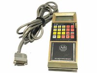
There is an old 1770-TB terminal with a 1770-FF personality module attached in the cabinet. Do you know if a copy of the program could be on this thing?

s-l300.jpg
 
that's the hand held programmer but it doesn't store the program when you use it you still had to back up the program with the tape deck.
did you try t open the renamed .LAD file in off line mode jus to have a look
if no it might be worth trying
just wondering now many racks are used I think the PLC2-30 only supports 7 or 8 the addressing is Octal
past time to upgrade you can upgrade without replacing the original racks there all remote anyway
 
I think that in the very old 1770-TA and 1770-TB and 1770-T3 terminal era, the only storage media was cassette tape on a 1770-SB data cartridge recorder.

The 1770-TB terminal might let you trigger a re-load from an EEPROM plug, but I don't think there was any onboard storage.

The presence of a set of backup files suggests strongly that there is a software package that will interpret or import them, so continue the search for whatever that might be.

The names Taylor and Teledenken might lead you somewhere; Taylor Industrial Software had alternative programming packages for A-B and Modicon controllers in the 80's and Teledenken made a PC-based competitor and I think was in the PLC-2 alternative software business at one point.
 
Thanks Gary and Ken.
I did try and open up the BAK renamed to LAD file and I got an error saying this is not a program file.

Attached is a rar of the contents of 1 backup disk. Maybe someone may recognize the extensions and what can open them.:geek:
 
Check inside the panel and see if there is a hard copy of program listing.
The PLC2 program is normally small enough that you can re-type them. Good luck.
 
The *.DFG file contained a MS-DOS encoded text file that turned out to be a ladder diagram printout. Formatted with Courier New font at 8 point size, with the orientation set for Landscape, it is reasonably readable in MS Word (attached, zipped).

I poked around in the other program files with a hex editor and did not find anything suggesting which software program created these files.

With that printout and AI-2, you may be able to just type in the program and load it into the controller. Fresh batteries, hot coffee, and a little good luck and you could have the system running tomorrow.

This is, of course, a *really good* opportunity to recommend an upgrade of the control system.
 
GTUnit - Ken
Did you look at the program while it short 289 rungs easy to type in.
But there are 65 file moves while each is just 4 words
it looks like they are moving recipe's for jobs they are selects from a thumb wheel input
unless you know the contents of each word in each file it will be difficult to know what to put in for each
The good thing is you know more now then you did before you started
you may be able to figure it out if you know the process
 
Gary, I admit I only looked at the first couple dozen rungs and didn't examine the thumbwheel-based data handling.

The labels on the thumbwheel input suggest that each of these settings is related to a barcode for a different motor oil product.

The Registers 1000-1003 appear as the destination of the 66 "File to File" moves starting on Rung 215.

Those registers, and the source range of data from 1016 through 1425 are part of the "expanded data table block 3" that you get access to when you install a larger RAM module in the PLC-2/30.

This would be equivalent to a COP instruction in a modern A-B controller.

Rung 193 shows Registers 1000-1004 being sent via Block Transfer to something at Rack 02, Group 5, Slot 0. Maybe it's a printer ?

I don't see anything in the files I examined that is obviously a data image of the PLC-2's memory.
 
I found that the L-A.CDS file includes (in reverse text) the part numbers of what are probably the installed I/O modules for this system:

1771-OA
1771-IA
1771-OFE2
1771-TTL
1771-DB
1771-DR


The good news is that the -OA and -IA are very simply 120V AC 8-point discrete modules.

The 1771-OFE2 was a popular analog output module.

The 1771-TTL is a low-level TTL interface.

The bad news is the other two.

1771-DB is a BASIC module, so it probably interfaced with a barcode reader or printer via its serial port. If the battery backup on that module was also dead, then that's another program backup that has to be sought out.

It shouldn't be complex; the -DB Series A and Series B were relatively simple BASIC52 interpreters, so the program is almost certainly a text file. You downloaded to them from the command line.

1771-DR is a special high-speed counter or "discrete logic" module. These are configured by sending block transfers to them, but if the source values for the registers that are transferred into it are lost, then the way it is configured is also lost.
 
Ken
What slot is the Basic module installed in my guess in Rack Group 5 Slot 0
the basic module could read and write to different devices maybe a printer
I doubt they used a barcode reader the were very rare when the PLC2 were used
the additional bad news is the Basic Module is programmed separately using terminal emulator using quick basic I have done a number of those in the old days
it may have to be reprogrammed but with out knowing exactly what was there it would be interesting and challenging to program it out
a high speed counter tell me that they are using a pus output flow meter most likely to measure one or more liquids dispensed into a batch. Again I have done a few myself.
with all that I really think you would be better served to reengineer it using a Compact Logix processor even if you can get this one running parts are limited and those you have are ageing you are just waiting for a failure and have to do it all over again
 
After looking at the program again
It is an oil bottle filling station, different brands and different grades of oil
They are using 2 racks, 1 and 2 all racks on a PLC2-30 are remote
I don’t think all of the IO is listed in printout
I would say the analog output is Rack 2 slot 3 Address 230
The analog module is only wrote to no read
The Basic module and the High Speed counter are in Rack 2 Slot 5 and Rack 2 slot 7

I can’t tell witch one is in each
Whoever wrote the original use the output table (000 -077) for data storage it works but you need to be careful I have had to do the when I ran out words in the data table
Just as a note the input table is (100-177) both should always be reserved.
Also on Timers and Counters the Preset value is stored in the address and the ACC value is stored in the address + 100 ( Timer 210 Preset value is in address 210 the Acc value is in address 310 )
Be careful that you don’t overwrite the values.
The addressing is in Octal 0-7 no 8 or 9 and all data values are 3 digits only max 999 the high order bite is used for status
If you are wondering you can do 6 digit math in the ladder code it complicated but it works.
I would think the Basic module writes the date and other information to an inkjet printer to print on the bottles.
The High speed counter and it’s dedicated outputs are used to control the fill valve
You write the preset pulse count to the counter module for each product.
They are setting the speed of something (I would think a VFD of some kind) using discrete outputs

As I said before it time to upgrade to a new processor righting the code would be fairly straight forward
You would not need the Basic module as the data to the printer could be setup within the Logic code
I hope this helps you understand what you are dealing with
I have spent a lot of time programming and troubleshooting the PLC2 and PLC3
 
Thanks for digging into this guys. Oy, I will try re-entering the code based on the printout.
Hopefully Its as simple as copying whats in the printout. The TTL card on Rack one is totally disconnected. They have a small box spray printer.
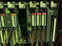
Here is what rack 2 looks like: All the other cards are discrete 120V IN or OUT.
I have experience on multiple platforms but Zero on PLC2.

Rack2.jpg
 
Last edited:
Thanks for the photo !

The red "Battery Low" LED on the 1771-DB BASIC module suggests its program is gone too.

The Rack 2, Group 5, Slot 0 makes sense for the 1771-DB; you see the Block Transfer Read/Write instructions on Rungs 192/193 addressed to "250".

Similarly, the Block Transfer Read/Write instructions on Rungs 190/191 are addressed to "270", so that's the Slot 7 Group 0, the 1771-DR.

Without a listing of the data values stored in memory locations 512- 542, it's going to be tricky to figure out how to configure that module.

It's not an enviable challenge, especially when the scope is "fix this obsolete system" not "retrofit this with a control system that has modern tools".
 
God luck
I don't see where the rebuilding the old system is a good idea
None of the modules or the processor are supported anymore the next failure will mean you have to do it all over again
it will take the same amount of time to build up a new Logix system as it will to get this up and running and you still have an old obsolete system that you will have to do it all over again
 

Similar Topics

F
I'm trying to use a PC to program an Allen-Bradley PLC2/02. I have the PLC, and I have a 1771-KE Communication Controller Card. I also have Taylor...
Replies
1
Views
5,069
OK, so I have seen the threads pop up and I had been doing some research into getting over this hurdle for a bit after I ran into some of these...
Replies
3
Views
868
Hello, I was wondering if anyone would be able to help me out; I have a PLC2 file that I can't access (I don't have the software). Would anyone...
Replies
3
Views
786
I want to start this by saying all the following is for curiosity sake only, no real world / production ramifications come along. Inspiration...
Replies
24
Views
6,215
Hello, I am using a Digi One IAP and CompactLogix PLC to read some Modbus registers from a Kohler Generator. Things are working, except when I...
Replies
1
Views
1,234
Back
Top Bottom