Micrologix 1400 Modbus TCP

rohit_plc

Member
Join Date
Jun 2013
Location
delhi
Posts
81
Iam facing a Problem in micrologix 1400 communicating with Modbus TCP.
I need to Read Some Register Data. on testing with modscan its showing Exception Response !!

Program file is attached !!

Any Help !!!

:confused:
 
Last edited:
Hello Rohit:
I am not familiar with the RSS extension you sent, but I am familiar with the Modbus protocol. if you could send me a Wireshark trace then I can see very clearly what is wrong with the query. If the Wirehark software is running on PC in which neither the Modbus TCP client nor the Modbus TCP server is running you would need an Ethernet TAP or managed switch with mirroring port functionality.
 
Rohit: I see, the RSS is the PLC program. If you could send the PLC program in PDF it would be good. I only have Logix 5000 so I cannot see your program, but the most useful would be to get the traces, as well as the specification of the Modbus TCP server device, which should indicate the supported Modbus commands and registers.
 
No need for Wireshark to get the exception code.

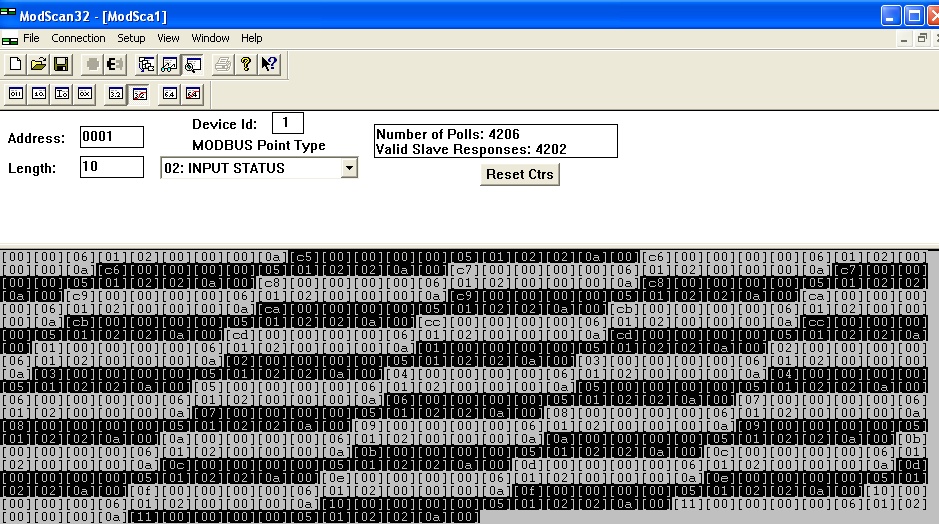
Modscan has a traffic display that will show the traffic:

traffic1.jpg


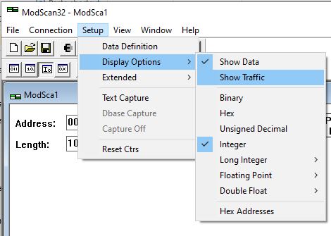
To select the traffic display: Setup - Display Options - Display Traffic

Display-Traffic-View-Setup-Display-Options-Display-Traffic.jpg
 
Rohit: I see, the RSS is the PLC program. If you could send the PLC program in PDF it would be good. I only have Logix 5000 so I cannot see your program, but the most useful would be to get the traces, as well as the specification of the Modbus TCP server device, which should indicate the supported Modbus commands and registers.

Please find the attached Pics

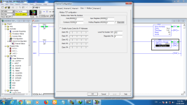
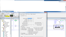
modbus1.png msg_chl.png msg_para.png test_Program.png
 
First you need to determine if your MicroLogix 1400 will be the Modbus/TCP "client" or "server".

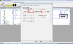
If it will be the "server" and you will have a software product like ModScan or an HMI as the "Client", you need to configure the Data File numbers that correlate with each Modbus data type. In your screenshot that shows the Channel Configuration, all of those fields are 0.

If your MicroLogix 1400 will be the "server", then you do not need to configure or execute a MSG instruction.

If your MicroLogix 1400 will be the Client, then your ModScan configuration needs to be set up as a server, not a client, and you will configure the MSG instruction to match its data addressing.
 
Rohit: As per Ken's very valuable insight, it seems your configuration will use the MicroLogix 1400 as the Modbus TCP client, and the other device is the Modbus TCP server. (Please double-check this)


If the MicroLogix 1400 is the client, then before trying to write a program for it, it is much easier first to use a Windows tool that has Modbus TCP client funcionality, such as Ken's first comment about Modscan.


So I recommend you get Modscan or another Windows Modbus TCP client tool, then confirm the functions and registers that are supported by the Modbus TCP server device. Make sure you can read or write those registers first with the Modscan, and then, proceed to test the Micrologix program.


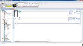
I cannot tell if your program is right or wrong because I do not the capability of the Modbus device. If the program did not work some parameter may be wrong. It seems that the program expects a device with IP address 192.168.10.6, TCP port 502 (very common in Modbus), register 40002, Modbus device address 1. As I said in an earlier post, we would need a Wireshark trace to see why you cannot get the communication to work properly properly but since this requires an Ethernet TAP, then the Windows client is a good choice.


Unfortunately, I cannot help with the screenshots you sent.
 
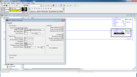
Your file named MSG-MG9 appears to be a setup page for a Modbus client, invoking Function Block 16 to Write multiple registers to server slave at 192.168,10.6 starting at Holding Register (4)0002.

File named Modbus1.png appears to be the server/slave basic memory allocation table for the MicroLogix. As Ken pointed out, none of the memory fields have been enabled (all set to zero), so there's no Modbus server memory allocated for Modbus registers to hold data values.

If the Modscan (client) is getting an exception response, it means that Modscan (client) is polling the uLogix (server) and getting a valid exception response, so communication physically works (the boxes can talk to one another), but Micrologix can not process a request for data from registers which are not valid Modbus registers so it replies with an error, an exception response.

No need to decode hexadecimal traffic to determine which exception code was sent, because basic setup is missing.

So, do you expect the MicroLogix to be the client/master or server/slave?
 

Similar Topics

I want to learn about modbus communication and I saw on another thread about inexpensive modbus relay units so I found it on Amazon along with a...
Replies
46
Views
7,230
I have a spare Micrologix 1400 Series B I bought used on Ebay awhile back. I had thought of it as a spare PLC for my train project but I screwed...
Replies
4
Views
1,256
Good Day! Would anyone be able to explain what is happening with the COP's and MOV's in this Modbus poll routine? If anything I am confused by...
Replies
6
Views
1,732
I been tasked with setting up communication between a heating cooling unit manufactured by Advantage Engineering and a Microloagix 1400 plc. The...
Replies
6
Views
2,513
Hi, I am trying to communicate between a MicroLogix 1400 and a Click PLC. There is a great video from AD that shows the simplicity of...
Replies
2
Views
1,771
Back
Top Bottom