4 wire vs 2 wire 4-20ma loop question

do you always connect the 4 wire one to 24 negative, or do i have to call each time and be berated?
 
I understand, I was saying in the case of this transmitter it has 4 wire, but the 4th wire is not a ground/return but a discrete output. In fact if he grounded that wire and it is a pnp version transmitter, then it would short.

Yes, I see what you are saying. I haven't looked at the wiring diagram for this particular instrument, I was just speaking generally of 2 wire vs. 4 wire transmitters. A digital output certainly wouldn't be connected to an analog input.

I've worked with some laser level sensors (K-Tek, now owned by ABB) that only provide 3 terminals to connect both the power supply and the analog output. This is not a problem when the instrument power supply is also the loop excitation power supply. Then again, some 24 VDC 4 wire transmitters will provide 4 connection terminals, even if the 2 common terminals are electrically identical. An AC powered 4 wire transmitter will always require a 4 terminal wiring configuration.
 
If you are powering up the instrument, then you have to provide a return wire from the power supply.

return wire, duh.

i'm just confused on the feed wire sometimes being positive and sometimes being negative and not knowing how to know when w/o sounding like an idiot.
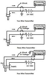
 
return wire, duh.

i'm just confused on the feed wire sometimes being positive and sometimes being negative and not knowing how to know when w/o sounding like an idiot.

I've found that many electricians are confused as to how 2 wire transmitters work, because of the nature of the series circuit wiring resulting in an analog input positive wire also being the return path to the power supply negative for the instrument's internal electronics.
 
Good question

This isn't a stupid question. Many people have been confused by 2-wir vs. 3-wire vs. 4-wire. I always make sure I cover this in my classes.

Note that many transmitters are 4-wire because the power draw is too high to take it from the 4-20 mA loop. Many 4-wire transmitters are AC powered.

loop types.jpg
 
ok, thanks for all the input. but i wasn't clear.
24 dc negative or 24 dc positive on the fee wire and why.
 
ok, let me get more clear.
i got a sensor in my left hand a sensor in my right hand. once needs to be connected to 24 neg and one needs to be connected to 24 positive. pretend i'm an idiot. how do i tell?
 
ok, let me get more clear.
i got a sensor in my left hand a sensor in my right hand. once needs to be connected to 24 neg and one needs to be connected to 24 positive. pretend i'm an idiot. how do i tell?
For a 2-wire sensor, it depends more on the input card than the sensor, I would say. Basically, you just need to have them in series, the proper ends connected to each other.
(I'm using 0V instead of 24vdc- as I find that confusing. Is it just the negative side of a 24vdc power supply, or 24v below the 0v mark, making 48vdc total from + to - of the circuit...)

Code:
+24v-----Sensor-----Input-----0V

Should work just as well as

Code:
+24v-----Input-----Sensor-----0V

Now, if your input card insists on one of its pins being tied to +24V or to 0V, then they are making the decision for you. But all a 2 wire sensor cares about is having one of its wires being toward the positive side of the circuit and the other being toward the negative side of the circuit. It doesn't really care which side the Input is located, just that it is in series.

3 and 4 wire sensors, you would need to look at a wiring diagram supplied with the sensor to know what it is expecting. Those are usually more picky about what wire goes where AND how the input card should be wired.
 
do you always connect the 4 wire one to 24 negative, or do i have to call each time and be berated?
1. In answer to the question above, a true 4 wire device requires a one wire to connect directly to the 24Vdc power supply (-)/return. That connection provides power to the device. But I doubt the Banner is a true 4 wire device.

2. The one or two Banner ultrasonic models that I've seen wiring for would be considered 3 wire transmitters, where the 24Vdc common (return) is connected to both the AI (-) and the Banner blue wire.

3. Point of interest: You can connect a 2 wire loop powered device directly to a power supply (xmtr (+) to power supply (+) and xmtr (-) to power supply (-), and the device will power up, but its output is useless because you haven't connected to an analog input.

4. It would expedite answers if you provided the exact Banner model number so we'd all know what kind of device it really is.
 
3 and 4 wire sensors, you would need to look at a wiring diagram supplied with the sensor to know what it is expecting. Those are usually more picky about what wire goes where AND how the input card should be wired.

If the transmitter is not a loop powered device, then it's analog output will connect in parallel to the analog input.

If the transmitter is a loop powered device, then it will connect in series with the external power supply (even if this power supply is built in to the analog input module) and the analog input.

Attempting to explain this to someone who doesn't grasp the difference between a series circuit and a parallel circuit is an exercise in futility, I suppose.
 
Maybe a picture will help a little.

Grounding the power supply is optional. ( I don't, but there are other treads for that debate)

analogWiring.jpg
 
Last edited:
If the transmitter is not a loop powered device, then it's analog output will connect in parallel to the analog input.

If the transmitter is a loop powered device, then it will connect in series with the external power supply (even if this power supply is built in to the analog input module) and the analog input.

Attempting to explain this to someone who doesn't grasp the difference between a series circuit and a parallel circuit is an exercise in futility, I suppose.

actually, this was the possibly the best answer thus far. would love to see the electronic diagram though.
 

Similar Topics

Hey, We have a 3-wire 4-20mA sensor that is connected to a display like this Now i need to connect this to a siemens ET200S analog input...
Replies
4
Views
2,917
Hi, May i know the how to know the minimum voltage to drive a analog input card. I'm connected to 4-20mA channel for 4 wire, supply voltage from...
Replies
3
Views
6,648
I have a SLC 500 PLC with NI4 analog input card. I am using two 4-20mA signal coming from an RTD transmitter. The overall length of the cable is...
Replies
6
Views
5,200
Does anyone have experience wiring this type of analog pressure transmitter up? It's 4 wires. 3 blacks and 1 green which I assume is earth...
Replies
9
Views
253
Hi everyone, I need some help I new with omron plc. I using plc CP1L. When I do the program it's good and the plc is function as program. But when...
Replies
1
Views
83
Back
Top Bottom