Ton Timer

Timers and counters are essentially the same thing...

Actually, Timers and Counters are Actually the same thing!

One is subject to a "regular" event (a timed update by the system).
The other is subject to relatively "random" events.

In many PLC's you can't have a Timer-12 and a Counter-12. This is because the "12" identifies a particular memory location in the Timer/Counter Memory Area.

Once you specify that the particular location is to be used as a Timer, that location is updated CONSTANTLY by the system. Part of the scan process is to bring in a copy of the Timer/Counter Memory area.

So, while the ladder is executing, it is working with a snap-shot of the Timer/Counter Table. That's why a Timer value doesn't change if you examine the value in the first rung and then again in the last rung.

If the memory location is specified as being a "Counter" then the "copy" of that memory location is subject to modification by the Ladder. The ladder can then reference that copy of the counter location and always get the latest value.

Now, at the end of the ladder, I think, the Timer/Counter Table is copied back to the original location through a MASK. The mask filters out all timer values. The value of each bit in the MASK is simply, 0=Timer, 1=Counter or Vice-versa.

Now, the original Timer/Counter Table has the latest Counter values AND, the latest Timer Values which were being updated all through the scan.

As someone already indicated, the particular timers are updated ("ticked") by the system. The system-cycles are counted by a counter which provides a pulse every so-many counts to another counter which provides a pulse every so-many counts to another counter... until there are .001, .01, and .1 type pulses.

Having identified a particular timer with a particular time-base, that timer watches for the specified pulse.
 
That implies that the more timer data spaces you have declared (ie with AB- the size or your T data tables) your scan time would increase, weather or not you actually used in a timer instruction. That would be interesting to know.
 
Terry:

Interesting theories. It brings up all sorts of experiments to try.


That's why a Timer value doesn't change if you examine the value in the first rung and then again in the last rung.

Therefore the code

MOV T4:0.ACC N7:0

...lots of code...

TON T4:0

.... lots more code, just to give a long scan time ....

MOV T4:0.ACC N7:1

EQU n7:0 N7:1 --- OTE B3/0

should result in B3/0 being ON, because the .ACC will not have updated during the scan.

Wow. I got to get me one of them PLCs thingies I keep hearing about to try this.


-----

The PLC then, in order to know which Timer (T-file word) to update, would have to have some flag(s) with which to know which timers are currently "running". Certainly the .EN bit (again, thinking AB here - please feel free to explain Siemens/TI structure).

If you're right, it would be possible to have a timer "time" (or "count", if you will), without a TON. Just use the techniques I posted earlier to manipulate the lower 7 bits (to give it an "elapsed time") and set the .EN and .TT bits, and watch it advance in the data table.

I don't know yet what good that would be, but it sounds cool.


Beginners - The stunts you are watching are being done by trained professionals. Please don't try this at home!
 
Yo, Allen,
.... lots more code, just to give a long scan time ....
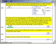
[attachment]Just JSR to this puppy whenever you need a pause.

For those who can't get enough of this stuff (Yes, I mean you, John) - take a look at the "Scan Times" under "Processor Status" while you play around with this. Warning to one and all, this is NOT the type of thing you want to do with your plant's production systems!

pause_loop.jpg
 
Neat trick, Ron.

I'm adding to my bag of dirty tricks.

Nice way to fault a processor on Watch Dog timer.

(When testing redundant PLCs, sometimes you WANT to fault a processor, just to watch the switchover happen.)

The longer this thread goes, the more I understand why Rockwell want's "Hands Off" on this stuff.

<img src="http://www.plctalk.net/qanda/images/smilies/fireskull.gif" height=75 width=75 alt="DANGER: Poison">
 
Great tangent!

Just want to back up what Ron B has been saying. The TON instruction should be viewed like a call to a subroutine that passes the timer's 3-word structure as parameters. The parameters are examined and manipulated by the routine and then returned (they are probably actually passed by reference and manipulated in place). Somewhere in the internals of the PLC is a 'heartbeat' timer/counter that is used for comparing and updating the timer's control word.
(4) the processor now checks to see if the Accumulator is "equal-to" or "greater-than" the timer's preset value. If either of these two conditions is true, then the processor turns ON the timer's Done bit.
Note "greater-than". This typically occurs with .01 sec timers when the program scan is longer than 10 msec. The resolution of the timer can be no finer than the scan time - unless, of course, you program multiple instances, in which case you better be very careful in how and where you use the done bit.

Another mystery:
While the above explains A-B's PLC-3 and later, how did the PLC-2 and earlier manage with only 2 words? Did they use a portion of the instruction word for the heartbeat?
 
Re: Re: Timers and book keeping

Allen Nelson said:


"How does the TON know how much time has elapsed since it was last scanned, and where does it store it?"


My theory. Then the TON is first enabled, the value of the free running clock (or some other clock) or at least the last eight bits are stored in the eight reserved bits in word 0 of the T file element.
Each time the T element is evaluated in a time instruction the CPU subtracts to tell how much time has elapsed and adds it to the .ACC. The new free running clock value is then stored in the reserved bits. It then compares to the .PRE to determine the done condition. Like you said, on a 10 ms timer 255 is 2.55 seconds. Way longer than a scan, so 8 bits is enough.

Look at the warning in the helpfile about putting timers in conditional subroutines. You could go longer than 2.55 seconds before calling it again and really messing up your time.
 
Last edited:
Re: Re: Re: Timers and book keeping

Rick Densing said:


My theory. Then the TON is first enabled, the value of the free running clock (or some other clock) or at least the last eight bits are stored in the eight reserved bits in word 0 of the T file element.
Each time the T element is evaluated in a time instruction the CPU subtracts to tell how much time has elapsed and adds it to the .ACC. The new free running clock value is then stored in the reserved bits. It then compares to the .PRE to determine the done condition. Like you said, on a 10 ms timer 255 is 2.55 seconds. Way longer than a scan, so 8 bits is enough.

Look at the warning in the helpfile about putting timers in conditional subroutines. You could go longer than 2.55 seconds before calling it again and really messing up your time.

I think Rick's theory is much closer to reality than Terry's. I would use the free running hardware counter to calculate the scan time at the begining of the scan. This is just the difference in reading n the hardware timer. Any scaling for milliseconds, seconds etc should be done here so it is done only once per scan. When the timer is initially enabled the timer is reset to 0. After that the scan time is added to the accumulated time each scan the timer is enabled. This accumulated time is compared to the preset to determine if the timer has timed out. This method is very efficient.

I am working on a project now where there is one 32bit free running timer running at 20 MHZ. When the timer is enabled, I save away the 32 bit timer. Each time the timer is checked, the initial time is subtracted from the current time and the result is compared to the timeout value.
 
I've done a few trials with the timer in a GE 90-30 PLC, and here's what I've learned:

The 90-30 uses a 3-word model for its timer, similar to AB. Unlike AB, the 90-30 does not have a designated timer memory. Instead, it uses three consecutive %R registers for each timer. The first of these registers holds the 'public' accumulated value, the second holds the preset vale, and the third is a control word. The upper four bits of the control word are enable, done, enable from previous scan, and reset. The presence of the two enable signals allows the same model to be used for both timers and counters.

The remaining 12 bits of the control word are a 'private' accumulator. Each program scan when the timer is enabled, it adds the scan time for the previous scan (in 100 microsecond increments) to the value in the 'private' accumulator. It then subtracts timebase increments (1, 10, or 100 milliseconds) from the 'private' accumulator, bumping the value in the 'public' accumulator each time, until the 'private' accumulator value is less than the timebase increment. If the 'public' accumulator value is greater than the preset value, it sets the done bit in the control word.

The 90-30 does not encode the timebase in the control word, so it must execute a different function call for each timebase.

If you program two timers with the same three registers assigned to both in the same program, when both timers are enabled, the value in the 'public accumulator will increase twice as fast as it should.

If you have a timer in a subroutine that doesn't get called every scan, the timer will still work OK so long as the subroutine gets called in less than approximately 400 milliseconds (12-bit 'private' accumulator of 100 microsecond ticks).

The backward jump that Ron Beaufort posted would also work in a 90-30, with the same results that Allen indicated if the timer preset exceeded the watchdog timer value (200 or 500 milliseconds depending on CPU model).
 
Reverse Engineering is every bit as much fun as PLC Programming!

Wow! This is long! And it exercised a lot of old grey-matter!

I do not proclaim this to be FACT!


My earlier post was thrown together in a hurry. I was leaving town. Just as soon as I had some time to consider what I said, I realized that it was woefully inadequate. The holes that I left in my post caused that post to present a very wrong picture of what I was trying to say.

Now that I'm back and have had a chance to re-read it... my description, as it stands, sucks!!!

First...
Buried somewhere in my post is "..., I think,...". This should have been at the top of the post and included a liberal sprinkling of "...maybe, perhaps..."

So...

I should think that one of the major aims of the PLC-designers would be to minimize scan-time as much as possible. There's nothing the PLC-designers can do to make a 1000-rung program run as fast as a 1-rung program. It's simply a case of, the more rungs, the more time. (This is true, in any case, except where the PLC-programmer uses Sub-routines or some-such, so as to prevent all rungs from being examined on all scans.)

So, the aim is to minimize scan-time.

In TI/S-7, there is a block of memory dedicated to Timers/Counters. As I indicated in my previous post, each "location" in that memory block is actually a Counter (what's that I smell off in the distance? Crow maybe?).

What is the difference between a Counter and a Timer?
A Counter counts "events". A Timer apparently keeps time.

What if the "events" that a counter is counting occurs every second?

The accumulated value in the counter increments by one every second. Isn't that the definition of a 1-Second Timer?

Soooo.... what's the difference between a Counter and a Timer?

The "thing", be it Counter or Timer, has no idea what the "trigger" is. It simply knows that the "trigger" was applied and so the increment occurs.

If the "trigger" occurs at apparently "random" times (i.e., not periodically, or, at a regular rate) then the device is a "Counter".

If, the "trigger" is applied in a "periodic" fashion (i.e., .001-sec, .01-sec, or .1-sec) then the device is a "Timer".

Many of us have already built "Timers" using "Counters" (other methods can, and have been used.).

I think, at this point, that I can get away with saying that there is no difference between the Timer & Counter Function EXCEPT in how the device is "triggered". While there might also be a couple of different "flags" associated with the particular selected function, there is still, basically, no difference.

Now... is it not the case that, when you want to "view" the current value of a timer, you must "tell" the interface that you want to "see" this timer value as a .1-Sec Timer Value, or a .01-Sec Timer Value, or a .001-Sec Timer Value?

That, alone, tells me that the Accumulated Timer Value is maintained at the particular memory location as a .001-Sec Timer Value. So, I think that means that all "Timer" memory locations are actually recording "time" in the smallest resolution that the system supports.

Assuming that the smallest resolution is .001-Sec, "1500" can mean only one thing; 1500 milli-seconds.

When a "Timer" is encountered in Ladder, it doesn't matter what the "declared type" (.1ms, or .01ms, or .001ms) is, the milli-second version of the "Accumulated-Value" is compared to the milli-second version of the "Preset-Value".

At that time, the decision is made, by Ladder, to SET or NOT SET the "Time Expired Bit". If it is SET, then all references to the Output of T-X, from that point forward, are read as TRUE. That is, the timer has expired.

Now, where is that damned "Time is Expired Bit"????

If "Timers", according to my scheme, are CONSTANTLY updated (assuming they are SPECIFIED AS TIMERS AND ENABLED <<-- I forgot to include that critical point in my last post),

AND IF...
As I also asserted, that reading a timer-value in the last rung produces the same result as reading the value of the same timer in the first rung,

AND IF...
Counters and Timers are essentially the same thing, and yet, counters can be incremented by Ladder ONLY, and Timers ARE NOT INCREMENTED BY LADDER, but the timer values seen by Ladder are only a Snap-Shot of the current values,

Then...
The "timed-out" flag MUST reside in a COPY of the Timer/Counter Table that was made prior to the execution portion of the scan!

IF, and this is a BIG IF, IF that is the case, then it must be that the Timer/Counter Table is COPIED back to the original table through a MASK, where the mask allows ALL Counter Values to be copied back to the Timer/Counter Table, as modified by Ladder, and ONLY the Timer Staus bits, as determined by the incidence of timer-functions.

The Timer Values are NOT RE-copied back because the Current Timer Values, which are CONSTANTLY updated in the Original Table, are MORE VALID!

Now, as far as Allen's question....

I should certainly expect that, if you...

early in the scan, copy the current value of timer-X to v-mem-X,

...and then, later, the program runs into the timer-X function, at which point, the timer-function does what? It can only examine "Current vs. Preset", at which point it will SET or NOT SET "EXPIRED".

...then, later in the scan, another copy the current value of timer-X is made to v-mem-Y,

...then a COMPARE is made between v-mem-X and v-mem-Y, I would certainly expect that v-mem-X and v-mem-Y are seen to be the same!

Do you NOT see this to be so????
If not, then please explain.

In the following, some timers tick-down while others tick-up. Modify as necessary to your particular timer-style.

If, however, you were to examine the "timed-out" status before the Timer-Function occurred, AND the Accumulated-Value was less than the Preset-Value, then I should expect that the result would be FALSE (i.e., NOT Timed-Out).

If, on the other hand, you were to examine the "timed-out" status after the Timer-Function occurred, AND the Accumulated-Value was equal to, or more than, the Preset-Value, then I should expect that the result would be TRUE (i.e., Timed-Out).

This is a "SWAG". There is more in my mind... but you know what that damned MGD can do!
 
Terry,
Having never been exposed to TI/S7 programming, I have no idea how they handle timers - but I would be surprised if it is as you have postulated.

However, AB (and GE according to Steve) timers definitely do not work as you have described.
AB timer and counter data structures are identical (control, preset, and accumulator words) but are used differently. The timer function makes use of more of the control word than the counter function.

The words are 16-bit values (PLC5 & SLC500) and the numbers in the preset and accumulator represent either seconds or centi-seconds. Interpretation of the value is a PLC function, not an interface function.

A 1-second time base timer may appear to 'count' seconds because the PLC program scan is very short relative to 1 second. However, observation of a .01-second time base timer in a program with a scan time exceeding 10 msec. will show that the timer is ADDING scan intervals.

The accumulated value and the 'done' bit are updated when the timer instruction is scanned, not before or after. That is why, if two instances of the same timer instruction are scanned separated in time by more than the time base, the accumulator values will be different (with the 2nd instance possibly setting the 'done' bit). It is really no different from a single instance being scanned on consecutive program scans (except in GE apparently).
 
I think calling timers and counters the same thing is on the right track. However, that doesn't make a timer a counter. I think it is best to call them both "adders". Just with different triggers and "added" values.
 
I am a little suprised no one here really knows the correct answer.(At least for AB) It is just something that I took for granted. Wondered about, the shook my head an went on to the next real problem.
 
Terry:

I was aware that your posts included words "I think" and "I'm guessing". Until we get a PLC ASIC programmer to post, we won't know for sure.

But I agree, reverse engineering is fun.

Although I haven't used a Siemen's/TI S-7, I was aware that they do timers differently from GE and AB. They have, as you describe, specific registers for timers (which are shared with counters), and that it is possible to "run out of timers" when all those registers are used, where AB/GE have "any" register assigned to a timer, so you can have as many timers as register space (i.e, the memory limit of the PLC)

Let me try to paraphrase your theory - just to make sure we're all talking the same thing.

You think that there is a task, running paralell but independent of scan that examines the Timer/Counter register memory addresses.

That task must know whether the address is a timer or counter, so that it will only update timers, not counters.

It must know whether the timer is enabled (by the last scan of the PLC logic scanner) or not, so that it can knows whether to advance the "timing counter" on a pulse or not.

It must know whether the timer is done (by the last scan of PLC ladder logic scanner) or not, so that it can stop updating.

It must know the time base of the timer (as set up in the ladder logic), so whether it advances the "timing counter" on a 0.001-sec, a 0.01 or a 0.1 second pulse, which comes from it's own internal clock(s).

Hmmmmmm......

Maybe. Doing all this in the background would, I agree, help ease scan time.

When the "logic scanner" hits the timer, it just sets/resets the "enabled" and "done" flags. Under the scheme that AB/GE seem to use, it would do that and add "some number" of 10 msec counts to the lower byte of the control word. (We're still trying to figure out if that "some number" is the last scan time, or if a portion of a free-running clock is stored there and compared to the actual free-running clock, and any "roll-over" gets added to the accumulator and deducted from the stored clock.) This math would slow the processor down ever so slightly.

But.... How many timers (timer/counter registers) do you get with an S7-200? I'm just wondering how busy that task would have to be to keep track of all of them accurately if they were all timers, all enabled and all had a time base of 0.001.

By my interpretation of how you perceive the "timing counter", the background task would be updating the accumulated time regularly. Therefore, each instance that the code requested the accumulated time, it would be different.

A simple experiment would be to have ladder which would have the timer, grab the accumlator and stick in a register, lots of code (or something like Ron's delay where the PLC spins its wheels for a while) to allow the background task to increment the accumulator, and then gram the ACC again, in a different register.

If there is such a background task, the two registers will be different.

If the "elapsed time" is stored with the timer register (like AB/GE) and the logic scanner is doing the math updates, then you would expect those registers will be the same.

Do you agree?

Can we get someone to run this experiment?
 

Similar Topics

Hello everybody, Since my experience is mainly with AB ladder I am having little bit of a problem with EasySoft.. Does anyone knows is there a...
Replies
4
Views
828
Does anyone know of a library that already has a implemented RTO? I was going to write my own but I'd rather not take the time.
Replies
35
Views
11,324
Hi there i was wondering if we can change in the TON the ms to min..... or how can i make a transformation... that shows up in c-more. cuz I am...
Replies
8
Views
2,144
All, I've got a TON that keeps resetting itself even though the rung remains true, I've slammed my head over this for some time now and cant...
Replies
16
Views
4,646
Ok guys I have a strange one. I just added a timer to to ML 1400 program, and it is not accumulating anything. But the OTE after the XIC TT...
Replies
6
Views
2,000
Back
Top Bottom