Logix guy with a new Step 7 project

PatrickG

Member
Join Date
Mar 2010
Location
Buchanan, MI
Posts
8
Hi Everyone,

I have a question for the Siemens programmers here.

I have been trying to recreate some of my ControlLogix boiler-plate in Step 7 and have noticed something strange. Maybe it’s just strange to me. I’m sure I’m doing something wrong.

I have two UDTs I like to use. One for the machine state (manual, automatic, etc.) and one for actuators. I happily wrote a function block with these two variables in the in/out interface. There was “Machine” of “typeMachine” and “actCylinder” of “typeActuator”.

Using this approach the block size is around 2k bytes. I thought “Wow that’s big. I’ll only be able to have 6 or 7 actuators per function block.”

Then I tried something else. I created a global DB with “Machine” and “actCylinder” in there. I made everything in the FB point at the global DB and took “Machine” and “actCylinder” out of the in/out interface. The block size went down to 626 bytes and the global DB was 180 bytes.

This approach seems to leave room for around 25 actuators. That seems better but I would like to understand why there is such a large difference.

My programs are printed out in this pdf if you care to look.

Thanks,
Patrick
 
Could you rather post a library of the blocks in both versions.
Not exactly clear to me what the difference was of both versions.
I think that in the 1st version you mentioned, by passing a UDT via i/o pins, the adressing inside the FB is passed as pointers.
In the 2nd version, the addressing is by absolute address.

I think that what I would have done, is to declare the UDT data in the STAT area in the declaration part of the FB. The data then becomes part of the instance DB for the FB.
When you call the FB,you have to assign it an instance DB.
This is the typical way to program FBs, and is also quite efficient.
 
Patrick,

Why dont you just define the IN's (switches...etc) and define your OUT (actuators..etc) Inside the FB.
Write your code around those (not i0.0 or q's)

Also use STAT for timer (multi-instance)

and viola---- your done

Call the block 25 times with a instance data for each...

of am I missing something special your trying to do?
 
When you declare an entry in the IN/OUT section of an FB, the following processing would be expected:

Assign values in the UDT
Call the FB
The FB processing reads/writes data in the UDT
The FB completes
Use the data written in the UDT for further processing

Is this how you use the UDT in ControlLogix ?
 
Thanks for taking time to help me!

I think that in the 1st version you mentioned, by passing a UDT via i/o pins, the adressing inside the FB is passed as pointers.
In the 2nd version, the addressing is by absolute address.

Correct.

I think that what I would have done, is to declare the UDT data in the STAT area in the declaration part of the FB. The data then becomes part of the instance DB for the FB.
When you call the FB,you have to assign it an instance DB.
This is the typical way to program FBs, and is also quite efficient.

Yes, I see that this way the block size is now 422 bytes. I also see that the instance DB can be accessed from other blocks. Is this normally accepted practice? As a rule in other languages I would not try to access a subroutines local data directly.

Why dont you just define the IN's (switches...etc) and define your OUT (actuators..etc) Inside the FB.
Write your code around those (not i0.0 or q's)

I wasn't really trying to create a FB for a single machine actuator. It's just the block that I chose to start with. I'll do this if I have a high number of actuators that are exactly the same.

Also use STAT for timer (multi-instance)

Could you explain this?

When you declare an entry in the IN/OUT section of an FB, the following processing would be expected:

...

Yes, this is what I would expect. Why is this the least efficient method with memory?

[QUOTE='L D[AR2,P#0.0];Is this how you use the UDT in ControlLogix ?[/QUOTE]

Actually I rarely use subroutines or add-on instructions (passing parameters) in Logix.

I use the UDT to create data structures for various "objects" such as a machine actuator, a screen on a PanelView, the I/O image of a valve bank on fieldbus, etc.

Again, thanks for your help!
Patrick
 
Yes, I see that this way the block size is now 422 bytes. I also see that the instance DB can be accessed from other blocks. Is this normally accepted practice? As a rule in other languages I would not try to access a subroutines local data directly.
The variable part of the declaration (STAT section) can be accessed from anywhere outside the FB. To do it or not to do it is can be the source of heated argumentations. But I do it routinely, and with zero problems whatsoever.
I cannot see the big difference to do it like this, and to use UDT structures in global DBs.
I have for example "Conveyor_33A".cmd.start which I use to start a conveyor from outside the FB.
And there are status information like "Conveyor_33A".sta.running, and "Conveyor_33A".sta.error that can be queried outside the FB.

The "local data" of the declaration (TEMP section) cannot be accessed from anywhere outside the FB or FC.

STEP7 does not have a "protected" variable part of the STAT section. This is sometimes called "local data" in other languages. That STEP7 doesnt have this can be viewed as a deficiency, but that is how it is.

A tip: Since you are using UDTs, which implies symbolic adressing, then I strongly recommend to use "symbolic address priority". Just in case you havent selected this already. It is very important when managing code that is derived from other code, that be multiple instance FBs, or UDTs.
 
The reason the IN/OUT udt generates so much code is that the UDT is passed by pointer, not by value. Each access to a udt variable has to be de-referenced.

If the UDT is passed as an IN or OUT or declared in the STAT section, the udt is passed by value (the udt is copied into/from the fb's instance data in the case of IN or OUT).

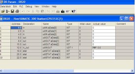
See example instance DB below:

idbidb.JPG
 
Originally posted by L D[AR2,P#0.0]:

The reason the IN/OUT udt generates so much code is that the UDT is passed by pointer, not by value. Each access to a udt variable has to be de-referenced.

Since a UDT is in effect a continuous unit isn't this more of a base+index kind of operation? I would think all the references would be calculated at compile time and basically converted to fixed references.

Keith
 
Here's an example of why so much code is generated.

A simple load as follows

Code:
 L     #udtINOUT.aData[0]

Gets executed as follows:

Code:
      T     LD     0
      TAK   
      T     LD     4
      L     DIW [AR2,P#12.0]
      T     LW     8
      OPN   DB [LW     8]
      L     DID [AR2,P#14.0]
      LAR1  
      L     LD     4
      L     LD     0
      L     W [AR1,P#0.0]
 
I don't know if your example isn't what you wanted to use or if it doesn't matter in Step7, but
L #udtINOUT.aData[0]
is an access to a fixed address. Why would Step7 go through all the gyrations when this compiles down to a fixed address access? I could understand the multiple dereferences if the line was

L #udtINOUT.{#UDT_Element}[#Array_Element]

With that you have two variables to dereference to find the address. But if you are just using fixed address elements of an IN/OUT paramter why does the operating system have to jump through hoops the compiler can take care of for you?

Keith
 
The FB is passed a DB pointer to the base of the UDT - all of the code (except for the last line) is setting up the DB and address registers ready to access the data in the UDT.

I can't see any other way to do it with the S7 architecture.
 
Will this work?

I want to copy 12 bytes to the "i" struct starting from I 32.0 and 12 bytes from the "q" struct to Q 32.0.

Code:
FUNCTION_BLOCK "fbFanIoTest"
TITLE =
AUTHOR : Edge
VERSION : 0.1


VAR
  Enable : BOOL  := TRUE;	
  i : STRUCT 	
   CommandEnable : BOOL ;	
   SystemReady : BOOL ;	
   ProgRunning : BOOL ;	
   Paused : BOOL ;	
   Held : BOOL ;	
   Fault : BOOL ;	
   AtPerch : BOOL ;	
   TPEnabled : BOOL ;	
   BATALM : BOOL ;	
   Busy : BOOL ;	
   ACK1_SNO1 : BOOL ;	
   ACK2_SNO2 : BOOL ;	
   ACK3_SNO3 : BOOL ;	
   ACK4_SNO4 : BOOL ;	
   ACK5_SNO5 : BOOL ;	
   ACK6_SNO6 : BOOL ;	
   ACK7_SNO7 : BOOL ;	
   ACK8_SNO8 : BOOL ;	
   Snack : BOOL ;	
   Reserved : BOOL ;	
   do_245 : BOOL ;	
   do_246 : BOOL ;	
   do_247 : BOOL ;	
   do_248 : BOOL ;	
   do_249 : BOOL ;	
   do_250 : BOOL ;	
   do_251 : BOOL ;	
   do_252 : BOOL ;	
   do_253 : BOOL ;	
   do_254 : BOOL ;	
   do_255 : BOOL ;	
   do_256 : BOOL ;	
   RefPos01 : BOOL ;	
   RefPos02 : BOOL ;	
   RefPos03 : BOOL ;	
   RefPos04 : BOOL ;	
   RefPos05 : BOOL ;	
   RefPos06 : BOOL ;	
   RefPos07 : BOOL ;	
   RefPos08 : BOOL ;	
   RefPos09 : BOOL ;	
   RefPos10 : BOOL ;	
   do_11 : BOOL ;	
   do_12 : BOOL ;	
   do_13 : BOOL ;	
   do_14 : BOOL ;	
   do_15 : BOOL ;	
   do_16 : BOOL ;	
   PrgStartAck : BOOL ;	
   PrgBusy : BOOL ;	
   Complete : BOOL ;	
   SpeedOverrideEnabled : BOOL ;	
   do_21 : BOOL ;	
   do_22 : BOOL ;	
   do_23 : BOOL ;	
   do_24 : BOOL ;	
   Auto : BOOL ;	
   T1 : BOOL ;	
   T2 : BOOL ;	
   Estop : BOOL ;	
   InputsSimulated : BOOL ;	
   do_30 : BOOL ;	
   do_31 : BOOL ;	
   do_32 : BOOL ;	
   ContinueAck : BOOL ;	
   do_34 : BOOL ;	
   do_35 : BOOL ;	
   do_36 : BOOL ;	
   do_37 : BOOL ;	
   do_38 : BOOL ;	
   do_39 : BOOL ;	
   do_40 : BOOL ;	
   do_41 : BOOL ;	
   do_42 : BOOL ;	
   do_43 : BOOL ;	
   do_44 : BOOL ;	
   do_45 : BOOL ;	
   do_46 : BOOL ;	
   do_47 : BOOL ;	
   do_48 : BOOL ;	
   ri_1 : BOOL ;	
   ri_2 : BOOL ;	
   ri_3 : BOOL ;	
   ri_4 : BOOL ;	
   ri_5 : BOOL ;	
   ri_6 : BOOL ;	
   ri_7 : BOOL ;	
   ri_8 : BOOL ;	
   do_57 : BOOL ;	
   do_58 : BOOL ;	
   do_59 : BOOL ;	
   do_60 : BOOL ;	
   do_61 : BOOL ;	
   do_62 : BOOL ;	
   do_63 : BOOL ;	
   do_64 : BOOL ;	
  END_STRUCT ;	
  q : STRUCT 	
   IMSTP : BOOL ;	
   Hold : BOOL ;	
   SFSPD : BOOL ;	
   CStopI : BOOL ;	
   FaultReset : BOOL ;	
   Start : BOOL ;	
   Home : BOOL ;	
   Enable : BOOL ;	
   RSR1PNS1 : BOOL ;	
   RSR2PNS2 : BOOL ;	
   RSR3PNS3 : BOOL ;	
   RSR4PNS4 : BOOL ;	
   RSR5PNS5 : BOOL ;	
   RSR6PNS6 : BOOL ;	
   RSR7PNS7 : BOOL ;	
   RSR8PNS8 : BOOL ;	
   PNSStrobe : BOOL ;	
   ProdStart : BOOL ;	
   di_243 : BOOL ;	
   di_244 : BOOL ;	
   di_245 : BOOL ;	
   di_246 : BOOL ;	
   di_247 : BOOL ;	
   di_248 : BOOL ;	
   di_249 : BOOL ;	
   di_250 : BOOL ;	
   di_251 : BOOL ;	
   di_252 : BOOL ;	
   di_253 : BOOL ;	
   di_254 : BOOL ;	
   di_255 : BOOL ;	
   di_256 : BOOL ;	
   di_01 : BOOL ;	
   di_02 : BOOL ;	
   di_03 : BOOL ;	
   di_04 : BOOL ;	
   di_05 : BOOL ;	
   di_06 : BOOL ;	
   di_07 : BOOL ;	
   di_08 : BOOL ;	
   di_09 : BOOL ;	
   di_10 : BOOL ;	
   di_11 : BOOL ;	
   di_12 : BOOL ;	
   di_13 : BOOL ;	
   di_14 : BOOL ;	
   di_15 : BOOL ;	
   di_16 : BOOL ;	
   PrgStart : BOOL ;	
   PrgBusyEcho : BOOL ;	
   PrgCompleteEcho : BOOL ;	
   SpeedOverride1 : BOOL ;	
   SpeedOverride2 : BOOL ;	
   di_22 : BOOL ;	
   di_23 : BOOL ;	
   di_24 : BOOL ;	
   di_25 : BOOL ;	
   di_26 : BOOL ;	
   di_27 : BOOL ;	
   di_28 : BOOL ;	
   di_29 : BOOL ;	
   di_30 : BOOL ;	
   di_31 : BOOL ;	
   di_32 : BOOL ;	
   ContinuePrg : BOOL ;	
   di_34 : BOOL ;	
   di_35 : BOOL ;	
   di_36 : BOOL ;	
   di_37 : BOOL ;	
   di_38 : BOOL ;	
   di_39 : BOOL ;	
   di_40 : BOOL ;	
   di_41 : BOOL ;	
   di_42 : BOOL ;	
   di_43 : BOOL ;	
   di_44 : BOOL ;	
   di_45 : BOOL ;	
   di_46 : BOOL ;	
   di_47 : BOOL ;	
   di_48 : BOOL ;	
   di_49 : BOOL ;	
   di_50 : BOOL ;	
   di_51 : BOOL ;	
   di_52 : BOOL ;	
   di_53 : BOOL ;	
   di_54 : BOOL ;	
   di_55 : BOOL ;	
   di_56 : BOOL ;	
   di_57 : BOOL ;	
   di_58 : BOOL ;	
   di_59 : BOOL ;	
   di_60 : BOOL ;	
   di_61 : BOOL ;	
   di_62 : BOOL ;	
   di_63 : BOOL ;	
   di_64 : BOOL ;	
  END_STRUCT ;	
END_VAR
VAR_TEMP
  nRetVal : INT ;	
END_VAR
BEGIN
NETWORK
TITLE =

      A     #Enable; 
      JNB   _001; 
      CALL "BLKMOV" (
           SRCBLK                   := P#I 32.0 BYTE 12,
           RET_VAL                  := #nRetVal,
           DSTBLK                   := #i);
_001: NOP   0;
NETWORK
TITLE =

      A     #Enable; 
      JNB   _002; 
      CALL "BLKMOV" (
           SRCBLK                   := #q,
           RET_VAL                  := #nRetVal,
           DSTBLK                   := P#Q 32.0 BYTE 12);
_002: NOP   0; 
END_FUNCTION_BLOCK

Thanks,
Patrick
 
Yes it does - you will have to rename your structures i and q as the editor will think they are referring to inputs and outputs when your try to refer to q.Hold for example.

Use ii and qq instead.
 
Last edited:

Similar Topics

Hey fellas, Our facility is still mainly PLC 5 and SLC, but we do have one, recently updated system with a ControlLogix processor. The tech guys...
Replies
6
Views
13,081
How do I organize the template for my controls. I am new to Logix Designer but have used RS500 and RS5000. My new Logix Designer has Toolbars...
Replies
6
Views
85
I am completely stuck on building a ladder program that requires a start button to be pressed 3 times to turn on motor 1. Then motor 2 starts...
Replies
20
Views
498
Good evening. I display the step number of a SFC on a display. Sometimes, on a trip, it goes quickly through many steps and I need to prove to...
Replies
1
Views
100
Back
Top Bottom