Hydraulic systems prone to oscillations

Adenitz

Member
Join Date
Feb 2010
Location
tir
Posts
41
Hello automation experts,

can someone explain me why hydraulic systems are prone to oscillations? I can understand this on a simple example with mass on a spring. It is natural to understand why there are oscillations if some initial force is applied to the system.

But I cannot understand why the same phenomena is present with oil hydraulic systems. Oil cannot be compressed like spring can. I know that in order to control something, one must first understand it. I hope you'll be able to help me understand.

Thank you very much!
 
The oil can not be compressed but the air can.

Make sure there is no air left behind.

Probably you need to bleed that air
 
I don't have exact application, just trying to understand the underneath physics.
I have found this explanation: "When a large mass is accelerated or decelerated during actuation, these inertia tendencies cause oscillations in the pressure of the hydraulic fluid and the rate at which the mass is moved. Accordingly, the components of the machine can “bounce” when actuated."
I'd like if someone can explain this better. Hydraulics is really counter-intuitive to me.
 
If a mass is accelerated and abruptly stopped the inertia can cause cavitation problems.

Examples in which this can happen is with a single acting cylinder that raises a load and stops suddenly, also as the sealing gaskets are not prepared for negative pressures it may happen that air enters the circuit.

Another case may be when double acting cylinders are used and the flow restrictors have been installed incorrectly on the intake side and not on the exhaust side
 
Last edited:
Originally posted by Adenitz:

Oil cannot be compressed like spring can.

Oil can be compressed. It just has a higher spring rate than the coil springs you are thinking about. All that means is that the system natural frequency will be higher than it would be with the spring you are thinking about.

The equivalent of spring rate in fluids is referred to as bulk modulus. If fluids were incompressible the value of bulk modulus would be infinite.

Another contributing factor is the stiffness of any hoses in the system. Hoses change their dimensions in response to pressure changes. This just provides another location for energy storage in the system, like having another spring connected to he mass.

So, as you can see, there are plenty of springs to deal with in that "completely stiff" hydraulic system even before you get to things like entrained air and cavitation.

Keith
 
Ditto what Keith said.
There are formulas for calculating the natural frequency of a cylinder and load. Accelerating or decelerating at a frequency close to the natural frequency is asking for trouble unless you have a very good hydraulic motion controller. Hydraulic motion controllers must be a little more sophisticated than servo motor controller because a hydraulic system is modeled as a mass between to springs so it is naturally under damped. A motor just has inertia assuming the R/L time constant is very fast.


https://deltamotion.com/peter/Mathcad/Mathcad - Natural Frequency Metric.pdf
I need to update that.


Here is a video of a hydraulic system that is intentionally designed to be difficult to control. The large mass relative to the cylinder diameter and hose between the valve and cylinder reduce the natural frequency. The sled is on rails so the friction is low. This reduces the damping factor. A normal PID controller with velocity and acceleration feed forwards cannot control this system well. The gains and speed must be reduced. However, out techniques allow compensating the the low natural frequency and damping factor.

https://deltamotion.com/peter/Videos/NF-FOA.mp4


The frequency of acceleration should be about 1/4 of the natural frequency when using a PI(D) with velocity and acceleration feed forward. In the video I am accelerating the load at 5 Hz with a 6.5Hz system. This is a ratio of much higher than 1/4.
 

Dear Sir,
is it possible to draw sketch of the system so I can visualize this cylinder that you're referring to in your calculation?

Thank you.

P.S. I have seen the video. It is very impressive, but I'm not really sure about this double derivative gain. Does it means that you use P+I+D+D^2 control (you calculate derivative of differential component of your PID controller)?
For someone who is not really familiar with this software, it is hard to understand.
Why green line (control output) is such noisy? I think actual actuator and mass cannot move the way green line is changing.
 
Last edited:
Dear Sir,
is it possible to draw sketch of the system so I can visualize this cylinder that you're referring to in your calculation?
You don't want to design the system like we did. We designed our system to be difficult to control. You want to design your system to be easy control.


We make hydraulic servo controllers. You can get a design guide here
https://deltamotion.com/


P.S. I have seen the video. It is very impressive, but I'm not really sure about this double derivative gain. Does it means that you use P+I+D+D^2 control (you calculate derivative of differential component of your PID controller)?
Yes! The second derivative gain is necessary on systems with low natural frequency and low damping factor like the one in the video.


You could design a system with a higher natural frequency and more friction for a higher damping factor so it may be possible to control with a normal PID with velocity and acceleration feed forwards but that gets expensive. The mechanical damping wastes energy and increasing the natural frequency requires either reducing the mass of the load or increasing the diameter of the cylinder. Increasing the diameter of the cylinder is costly because it requires more flow and bigger components.


[quote

For someone who is not really familiar with this software, it is hard to understand.
[/quote]
It shouldn't be. There are a target and actual position, target and actual velocity. The green line is the control output.


Why green line (control output) is such noisy? I think actual actuator and mass cannot move the way green line is changing.
The 'noise' isn't really 'noise'. It is due the the resolution of the feed back. The 0.000001 meter resolution can only calculate an acceleration rate with a resolution of 1 m/s^2
Since the second derivative gain is multiplied by the error between the target and actual acceleration and the actual acceleration has a resolution of 1m/s^2 then the control output changes in small jumps. The second derivative gain is important and this is something that most controllers do not have.


On top of that we can use our model based control where we use a model to compute the actual velocity and acceleration with floating point resolution. The elminate's most of the 'noise' due to resolution.


Use 1 micron feedback. Mount the valve directly on the cylinder. Size the accumulator properly and mount it by the valve.


BTW, PLCs couldn't possibly do this.
 
Dear Sir,
I was referring to your pdf file. You wrote it needed update. I hope this update means some drawing, because the pdf file contains variables which I cannot visualize. It would be really good example if variables were actually shown on a drawing. Is it possible that your pdf calculation is done for setup shown in video?

Do you measure position with resolution of 1 micron? What kind of sensor is used? It must be expensive.

Thank you very much for your time to explain and make calculation. I'll hope you'll update pdf file with some drawing.

Thank you once again.
 
Dear Sir,
I was referring to your pdf file. You wrote it needed update. I hope this update means some drawing, because the pdf file contains variables which I cannot visualize. It would be really good example if variables were actually shown on a drawing. Is it possible that your pdf calculation is done for setup shown in video?
There is nothing wrong with the pdf file as it is. The last two pages are just the rest of the equations from above. I am using Firefox to view the pdf file now. I would only add a few refinements after 14 years.

Do you measure position with resolution of 1 micron? What kind of sensor is used? It must be expensive.
Easy, use a Balluff or Tempsonic SSI magnetostrictive displacement transducer ( MDT ). These will provide 1 micron resolution.


Thank you very much for your time to explain and make calculation. I'll hope you'll update pdf file with some drawing.

Thank you once again.
Does anybody else have problems viewing the pdf file?
 
I can read it fine.

I don't think Adenitz is saying there is anything structurally wrong with the pdf. I think he is saying that he can't picture how the equations translate to a real physical system. The equations don't mean anything to him.

Keith
 
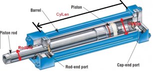
File opens fine! Just like Keith said, it is hard for me to visualize. I suggested that one picture of the actual system you're calculating would be fine.

P.S: I thought a drawing just like attached picture

Cylinder.jpg
 
Last edited:
I don't understand. The cylinder length, rod diameter and cylinder diameter are obvious.
You should know the mass that is being moved too.
Then there is the bulk modulus of oil which is an indication of how compressible the oil is.

Mount the valve on the cylinder for best result. The valve should be linear. There should also be an accumulator by the valve to keep the supply pressure as constant as possible.
 

Similar Topics

Well pardner, I can't speak for Alaric, but I is often wrong. Not this time, though. (Actually, I was kinda feelin' ornery and did my post partly...
Replies
36
Views
22,959
Hello everyone, I'm reaching out for assistance regarding a project I'm currently working on. Specifically, it involves a hydraulic system with...
Replies
7
Views
401
Hi All, I could do with some advice on a hydraulic control system. It is necessary for me to accurately position a vertical hydraulic ram with...
Replies
34
Views
1,908
Hi, I am about to start a project controlling a hydraulic ram using a Siemens S7-1200 controller. It will need to be quite steady control, by...
Replies
1
Views
757
Good Evening Everyone, I am attempting to monitor the level of hydraulic fluid in a tank. The tank is 50 gallons. For insurance purposes we need...
Replies
16
Views
4,168
Back
Top Bottom