CLX PIDE CV Hanging

Join Date
Jun 2015
Location
Somewhere
Posts
7
Hello,

I'm using the PIDE instruction for the first time. While it's not my first time tuning a PID, most of the other times in the past has been done with a PID instruction and I've just used simple tuning methods to dial it without becoming an "expert" at each of the terms.

For this project, a new facility and installation, I've using View distributed and am content with the process graphics library. The faceplates in that library utilize the PIDE instruction.

From what I gather, the difference here being a velocity versus position sort of calculation.

I have several different loops, some temperature control, others flow control, level control ect throughout this facility. I am still working on tuning of course, but I've noticed behavior that I have not noticed before.

Let's say I have a temperature that I am trying to regulated with chilled water through a control valve. At times, I've the CV has been at 0% or 100% The limits I've set) for a period of time, when the PV overshoots the CV will hang for what I believe is quite awhile (i.e., chilled water valve remaining 100% open when temperature overshoots to being under setpoint) sometimes for upwards of 1 minute before the CV starts responding to correct in the other direction.

All deadzone features are disabled or at 0.

I did some searching (here and google) before posting and I read some comments that referred to integral windup, wherein the i-term will continue to accumulate even though the CV is clamped. Which then means the accumulation would have to work it's way back down before the CV would change. It wasn't clear that if this applied to the PIDE instruction, because other comments/info I read indicates that i-term will stop accumulated once CV min/max is established.

Also, the i-term itself (for independent) are 1/sec for PID, and 1/min for PIDE. It's unclear to me if my i-term would be 60 times larger (sec to min) or 60 times smaller (min to sec) compared to a PID. It's likely that my i-term is set incorrectly.

For example, a loop that I am happy with at another facility using a PID instruction is kp=2, ki= 0.1, and kd = 0). Assuming all else being equal, if I
wanted to bring that into the PIDE instruction, would the ki need to be 6?

Sorry for the wall of text, appreciate any feedback.
 
Assuming all else being equal, if I wanted to bring that into the PIDE instruction, would the ki need to be 6?

yes, 0.100 (PID) would convert to 6.000 (PIDE) ...

if that doesn't work out for you, you might consider attaching your ENTIRE .ACD file to this thread (you'll have to zip it first - forum rule) ... maybe we can spot something that's keeping everything else from being equal ...

welcome to the forum ... hope this helps ...

Thanks. I don't have access to my software at the moment. In general though, it is a 100% unaltered (save for the gains, and few config options) Rockwell Process Graphics Library Faceplate with their AOI.

To make sure I'm not chasing a ghost, can you confirm if the i-term will continue accumulate when the CV is at either Max or Min? I found verbiage in the help files that indicates that i-term will freeze on the PID instruction, but I didn't see any confirmation if that holds true on the PIDE instruction.
 
To make sure I'm not chasing a ghost, can you confirm if the i-term will continue accumulate when the CV is at either Max or Min? I found verbiage in the help files that indicates that i-term will freeze on the PID instruction, but I didn't see any confirmation if that holds true on the PIDE instruction.

The incremental (or velocity) form of the PID computation does not accumulate integral action like the positional form, and will not "wind up" when clamped at an upper or lower limit. It would be helpful to see a trend chart of the undesired behavior (SP, PV, and CV) because the description of the behavior implies something else, beyond the unaltered PI action, is occurring (e.g., unintended feedforward action, external logic that directly manipulates CV, PIDE not being scanned, etc.). Basically, if the PV has overshot SP, and is continuing in that direction, the CV should be decreasing. In this situation the both the P and I terms will create negative incremental action, resulting in some decrease of the CV off of the limit.

Regarding the general observation of differing performance between the prior PID implementation and the newer PIDE (with appropriately recalculated gains): consider verifying that timing of the previous PID was correctly set. Specifically, that the loop update time parameter was equal to the time period between PID scans. Since the PIDE takes care of this for you, assuming timing mode Periodic, it will ensure the correct integration delta time. If the previous PID was incorrect, it will appear as a factor in the integral (and derivative, if used) gains.
 
Greetings Scubasteve2365 ...

regarding your question:

To make sure I'm not chasing a ghost, can you confirm if the i-term will continue accumulate when the CV is at either Max or Min? I found verbiage in the help files that indicates that i-term will freeze on the PID instruction, but I didn't see any confirmation if that holds true on the PIDE instruction.

the simple answer is that the Integral action of Allen-Bradley's PIDE instruction does not "windup" (i.e. continue accumulating) once the output of the PIDE reaches its maximum value ...

actually this same "windup" question gets quite a bit of traffic on the forum – so here's a little lab experiment to help nail down the idea ... hopefully this will be helpful to other members who might pass this way in the future ...

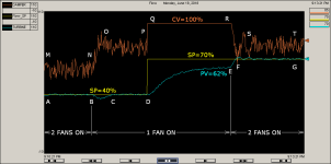
the 3-minute trend attached below shows the action of a simulated "Hotrod" training device that I use in some of my classes ... you can find a picture – and a down-and-dirty description - of the actual Hotrod at the following link ...

http://www.plctalk.net/qanda/showthread.php?p=65620&postcount=39

the experiment is being controlled by a 1756-L55 ControlLogix processor running version 16 of RSLogix5000 software ...

as the experiment begins at Point A, the PIDE's Setpoint is 40% - and the Flow through the Turbine is running along "on target" at 40% ... both of the Hotrod's fans are ON – and we're running in "normal" operation ...

the CV (Damper position) is dancing along at about 60% open between Points M and N - being controlled by the PIDE ... (note that the CV's "jitter" is caused by the Derivative action's response to the simulated noise on the PV – which I left turned ON for this experiment) ...

the sun is shining – the birds are singing – life is lovely ...

then at Point B, we upset the system by manually turning OFF one of the Hotrod's fans ... the PV (air flow) begins to drop, which causes the PIDE to increase the CV output signal – which opens the Damper wider to compensate for the loss of the turned-off fan ... we see the CV increase between Point N and Point O ...

at Point C the Flow has returned to the target of 40% - and the CV (Damper) now dances along at something like 78% ... so even with the loss of one of the fans, the PIDE is able to maintain its Setpoint (target) of 40% ...

so once again, the sun is shining – the birds are singing – life is lovely ...

then at Point D, we upset the system again – this time by manually giving a sudden "step-change" to the Setpoint from 40% way up to 70% ... (ouch!) ... the PIDE makes a noble effort to keep the PV on target – by further opening the Damper from Point P to Point Q ...

at Point Q, the PIDE has driven the output signal to its maximum of 100% (in simple terms, the Damper is now wide open) ... unfortunately, with only ONE fan available to move the Hotrod's air stream, we have a problem ... you can see the PV is trying its hardest to reach the target (bless its little heart) - but the highest PV signal that we can achieve with only ONE fan is about 62% of full flow – which we've finally reached at Point E ...

and now we come to the purpose of the experiment ...

we have before us a very common question: what is the PIDE doing to its Integral action behind the scenes right now? ...

specifically, is the PIDE constantly increasing the numeric value of the Integral action (in other words, is the Integral continuously "winding up" in the background) – even though the CV output signal has reached its maximum limit of 100% ???

in simpler terms, now that the PIDE has already shoved the "pedal-to-the-metal" – is the PIDE still stubbornly increasing - increasing – increasing its foot pressure on the gas pedal? ...

at Point E, we turn the second fan back ON again ... since the damper is already wide open, naturally the PV (flow) begins to rapidly rise from Point E to Point F ...

and here we see the answer to the question ...

notice that as soon as the PV (flow) begins to respond towards the target – the CV (damper) quickly begins to "drop off" at Point R ... specifically, we don't have to "wait around" for the Integral action to "wind down" before it can resume active control of the CV signal ...

so – from where I sit, it certainly looks like once the CV (output signal) has reached its maximum limit - the PIDE instruction does NOT "wind up" the Integral action ...

in closing ...

I have seen MANY programs in which the original programmer has jumped through a significant number of hoops – and generated a large amount of confusing code – in trying to prevent an Allen-Bradley PIDE (or a PID) instruction from "winding up" its Integral action ... as near as I can determine – based on this type of experiment - that's sort of like "chasing a ghost" as you said in your latest question ...

party on ...
.

no_windup.PNG
 
Last edited:

Similar Topics

I have an application using an eddy current coupling to transmit torque from an AC motor to a brake module. The coupling is needed so the AC motor...
Replies
3
Views
4,090
Hi, I'm trying to program a cascaded loop using PIDE to control the dewpoint of a room through a HVAC system. The problem i'm having is with the...
Replies
1
Views
1,515
Hi All I am trying to use RSLOGIX5000 PIDE block, and my starting point is the example that had been given on PIDE White Paper...
Replies
2
Views
7,366
Anyone here have experience with the PIDE block? I've got a system with 15 loops in it. The loops do not seem to react like I would expect them to...
Replies
12
Views
4,980
Controller: 1756-L84E v.35 Prosoft MVI56E-MNETC for ModbusTCP/IP I'm having an issue with some of my write commands. The write command that...
Replies
0
Views
186
Back
Top Bottom