Danfoss FC302 -- Mech. brake low [A63] -- No brake, why am I getting this alarm?

antsrealm

Member
Join Date
Dec 2010
Location
Brisbane
Posts
207
Hi,

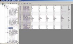
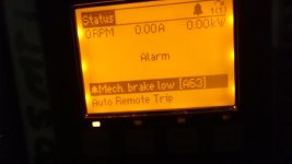
I have a small danfoss FC302 VSD giving a Mech brake low [A63] alarm once or twice a day for some reason. There is no brake and the only I/O wiring is a start signal and a relay output for 'fault'. None of the digital or relay outputs are set to mechanical brake and all the brake settings under 2-20 are set to zero.

Any ideas why this would be popping up ??

Thanks,
Tony.
resized.JPG
 
I would check the User Manual and look to see what causes the A63 Alarm to go on. It may be triggered by several other condition (or someone previously programmed it to go on when your existing fault relay goes on).

From the Danfoss FC300 User Manuaal, Page 89 shows that Alarm A63 is caused by Parameter 2-20. On Page 58, the Parameter 2-20 "Release Brake Current" default value is "ImaxVLT (P1637)" and it changes during operation. If you can figure out how to keep Parameter 2-20 at 0 or null, then the A63 warning should go away.

Reading farther, I don't think that Parameter P16-37 (ImaxVLT) is user-controlled, so that leaves one of the other mechanical brake parameters from 2-21 to 2-25. You should check the values of 2-21 and 2-22 "Activate Brake Speed". If you set P221 and P222 to some large speed (that the drive can never reach), then maybe that will prevent the mechanical brake function from being activated.
 
Last edited:
I would check the User Manual and look to see what causes the A63 Alarm to go on. It may be triggered by several other condition (or someone previously programmed it to go on when your existing fault relay goes on).

You did not mention any digital inputs. Some drives also have programmable digital input terminals that can be set for various functions.

A quick search shows that this Danfoss model has a built-in Smart Logic Controller. So any condition or combination could have been used to set any of the alarm outputs.

The only other input programmed other then the start input is the reverse input. and out of all the input terminals only the start is wired. I have read the manual and read all about the error 63 and it suggests that you have to have one of the outputs programmed to mechanical brake for the mechanical brake parameters to take effect. Since we don't have any outputs programmed for mechanical brake, I cant understand why we are getting this alarm.

I will look into the smart logic, that is something I haven't looked at yet.

Thanks for the feedback.
Tony.
 
I just checked the smart logic enabled parameter 13-00 and it is set to off.

Unfortunately that must not be the cause of this issue.
 
It appears that the mechanical brake outut may go ON by default. Check parameters 2-21 and 2-22. If these are set to the largest possible allowed numbers, then that should prevent the mechanical brake function from being activated (unless those speeds are reached). On the other hand, maybe "0" speed would cause the mechanical brake output to stay off.

Parameter 2-23 "Activate Brake Delay" defaults to 0 seconds. You could set that to 9999999999999999 or whatever the largest number of digits you can enter. That will help to keep that bogus warning from popping up.
 
Last edited:
Yeah I might have to try something like that. However I noted that in the relay function description in the manual (page 83) it says under Mech brake control, "Selection of mechanical brake control. When selected, parameters in parameter group 2-2* are active".

Since I don't have that selected on any of the outputs 2-2* should not be active ??
 
Yes, I think that means that 2-2 are only active if the mechanical brake is selected. Now which parameter selects the mechanical brake? Is it one of the programmable output terminals?

Here is the definition of the A63 alarm. If the "release brake" current was set to 0, that might disable the alarm. Check to see for what Parameters 5-30 and 5-31 are set. Maybe one of those are set for Mechanical Brake Output.

ALARM 63, Mechanical Brake Low:
The actual motor current has not exceeded
the “release brake” current within the “Start

delay” time window.


3.7.1. Mechanical Brake Control
In hoisting/lowering applications, it is necessary to be able to control an electro-mechanical brake:
• Control the brake using any relay output or digital output (terminal 27 or 29).
• Keep the output closed (voltage-free) as long as the frequency converter is unable to ‘support’ the motor, for example due to the load being
too heavy.


• Select
Mechanical brake control [32] in par. 5-4* for applications with an electro-mechanical brake.
• The brake is released when the motor current exceeds the preset value in par. 2-20.
• The brake is engaged when the output frequency is less than the frequency set in par. 2-21 or 2-22, and only if the frequency converter carries
out a stop command.
If the frequency converter is in alarm mode or in an over-voltage situation, the mechanical brake immediately cuts in.


Last edited:
Is parameter 5-30, 5-31, or 5-40 set to Mechanical Brake?

In my case terminal 27 & 29 have been setup as inputs and as a result I dont have 5-30 or 5-31 instead I have 5-13 & 5-12.

That sets...

Terminal 27 Digital input as [0] No Operation and

Terminal 29 Digital Input as [14] Jog

5-40 is set to [9] Alarm

as I mentioned earlier all the digital out and relay out settings are not set to mechanical brake. It's strage.

Thanks for the reply,
Tony.
 
if the FC302 run as normal application nothing special process,upload the program save the program and check/activate parameter for factory default and download as factory default,
for trouble shooting
 
5-40 is set to [9] Alarm
Apparently it is the 5-40 Function Relay that is causing the A63 Alarm. The Danfoss controller is erroneously intrepreting the [9] "Alarm Output with no warning" setting of 5-40 as [32] "Mechanical Brake Control".

You could try to reset this error condition by resetting 5-40 to [0] "No Operation". If that stops the A63 alarm, then you have found the source of the problem. I don't know how to correct it so that it sees a [9] instead of a [32].
 
I see this is a bit old, but did you solve the issue?

What SW is the drive? (can be seen in parameter 15-43)

You could try setting Par. 2-20 to the maximum value possible.
 

Similar Topics

Hello! First post here! Trying to commission a Danfoss FC302 frequency converter (with option A MCA121 EthernetIP-card) connected to ABB AC800M...
Replies
3
Views
1,247
Im working with Danfoss fc302, i got a simple problem inyet icant fixed it, can you help me, we had several drive in our project, to be able...
Replies
2
Views
2,011
Hello, At the company where I'm working for they have standard FB's for controlling FC302 drives. When we do not have a signal to the PLC from...
Replies
1
Views
2,023
Hello, I'm using a Danfoss drive FC302 connect via profidrive to a Siemens PLC 315. My problem is how can I read from the drive a current upper...
Replies
3
Views
2,183
Dear All I want to use Danfoss fc 302 Preset Refrence .can anybody guide me on this ...thanks in advance
Replies
2
Views
1,890
Back
Top Bottom