Using Bit Logic to Sequence

Why won't a company allow using sequencers? How can they even manage this? Is there an issue using sequencers in certain applications? Someone explain please.


My guess is that he's referring to drum sequencers, which is essentially like running your PLC sequence on a cam. It's a pretty old way of doing things, and can be really hard to troubleshoot.
 
I learned how to implement sequences on this forum. They taught me a couple very useful things:
First, use an integer address to store a number for the step in your sequence. Then use conditions to set the sequence.

Next, don't have your steps be "1, 2, 3", have them be "10, 20, 30" as you can THEN have 9 additional steps in between each step in case you need to add one.

Here are a couple things I have learned:
If you use a sequence like that, put a table of contents in the comments at the top of the logic that sets the sequence. Then you can label each step and use the find function to go to where you need to be much more quickly.

When doing your HMI program (once you get to that), you can use a multi-state indicator that can hold tons of different values based on the integer step of the sequence value.

when you are setting up the logic for your sequence, use OTHER sequence numbers as conditionals to enter a sequence. This provides really easy-to-understand interlocks to keep the system in cycle. For example: If (system in auto) && (current sequence == 1) then (turn on output, set sequence to 2)

Hope this helps.
 
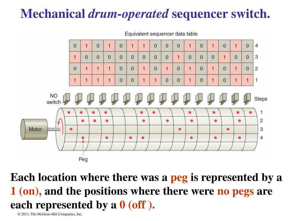
The original meaning of the word sequencer in PLC parlance referred to what is often called drum sequencers based on the original electromechanical sequencers that were much like a player piano. My first job in automation dealt with both the mechanical type and ISSC PLCs (predecessor to Honeywell) that used them in ladder logic. I looked for 20 minutes for an image of the infamous Tenor Stepper and came up empty. It was a drum with pegs powered by a little motor. When the advance signal was applied to the motor circuit, it would roll forward one step. At the bottom of the drum, there was a row of limit switches wired to rest of the machine. If there was a peg in that step, the switch would be activated causing some machine function to receive power. You would reprogram the sequence by looking rearranging the pegs in the drum. I'm getting old...Google no longer has pictures I could easily find.

In A/B ladder logic, the SQI/SQO instructions are based on this principle. They are are extremely powerful and can be designed to be incredible efficient and flexible. They also require some form of documentation to assist with troubleshooting. The simpler implementations don't sequence the inputs, only the outputs, but still offer indirect addressing of a mask file. I think that is the part that can be difficult for many maintenance personnel. You are dealing with at least two indirect addresses in a single instruction that you have to display or look up and analyze the bits to see what is going on.

What often happens is the original design is not well understood and then mods are applied outside of that design that turn it into a mess that ends up getting a bad rap and causes folks to just decide not to allow them any more.

If you sequence the inputs as well as the outputs, you can make diagnostics all but automatic with just a couple of more instructions and some well thought out HMI displays. Again, it is an abstraction that requires a thoughtful design, excellent implementation, good training, and good documentation to make it worthwhile. All those things can go out the window when people change jobs or outsiders without that insight are required to modify or troubleshoot the code.
 
Last edited:
Like this?
slide5-l.jpg
 
Yeah there are some funny old folks out there....
Here is another one, "I don't like set/reset", but to OR the output round the trigger logic & then use a not to reset it is basically the same thing
---| |----| |-|----|\|-----( ) O:1
O:1 |
---| |---------|

Only difference is the logic is on one rung better in my mind for debugging though.
I have seen it many times I once worked with a guy, we were doing some mods on an existing machine where there were a lot of SR instructions, he proceeded to replace them with the above as he did not like set/reset (huh!)
It was not as if the sets & resets were in different rungs.
I have been in this game for over 35 years and come across some bad logic in my time, sequence words are my favorite and have used them extensively.
My pet hate is where bits are set & reset many times through the program.
Sequence words have a number of advantages, you can enable a function (be it an output or call to another block in a range of the word i.e. enabled between 10 & 20, while enabling another output between 12 & 18 A good example is open block valve while seq is 10 to 20 start pump 12 & 18. so in essence make sure the valve is open before stepping on to start pump.
Other advantages being able to jump steps forward/back easily, and displaying process text on HMI or Scada.


I too have been "in this game" for many years, and can concur that a sequencer built using a word value as a "step number" offers more advantages than bit logic.

Here are some of them ....


1. Easy to see where you are in the sequence. You can only have one value in a single word.

2. The "step number" can be generated at functional spec writing stage, so the software corresponds to the spec.

3. You can only ever be on any one step at a time.

4. Step number values are retentive in all PLC types. Will always survive a processor restart. Many "bit-logic" sequencers will completely reset themselves at power-on unless using Set/Reset or Latch/Unlatch bits.

5. Easy to modify, especially if there are lots of "spare" steps inserted into the functional spec.

6. Jump forwards, backwards, perform iterative loops, etc., all very easy with a numerical step sequencer. Not so easy at all with bit logic.

7. The functions of "Step-On" and "Step-Jump" can be handled by a "Sequencer Engine" piece of code that is common to all sequences. The "sequence" itself is containerised in its own routine, making fault-finding and debugging a doddle

I'm sure there are more advantages, but that list will do for now ....
 
I totally agree Daba, The only things I will add is that on some PLC's not all words are retentive so either set them as or pick the range that is (example is Mitsubishi FX range 0-199 are not by default).
 
Another advantage of the numerical step sequencer I have just thought of is that it is so easy to "synchronise" multiple sequences or sub-sequences, just by looking at the other sequence(s)'s step number(s).

I have used that to great effect recently on a 6-axis stone slab cutting machine, where, for example, the "Unloader" has to be brought to a point of readiness, and wait there for the stone saw to have completed its cut and reached its "Parked" position.

Just a simple EQU Cutter_Step 200 instruction, job done !

And vice-versa, the Cutter can't start its return travel until the unloader has picked up the cut slab, and has commenced its return travel to the unload station. EQU Unloader_Step 54, again, job done !
 

Very cool find... I love the old school stuff, also like the limit switch on the right side (y) gives a whole new meaning to the definition of 'held open'

I worked on some large printing presses that were made in the 60's and found it amazing what they could do with pneumatics and mechanical switches
 
Imagine that (assuming this was programmable by moving/adding pegs) a disgruntled employee decides to spice things up before he leaves. :mad:
 
That rotary was in a machine we rebuilt (the before picture). I tried to keep the drum sequencer for show and tell but they took it back for a spare since they had more machines in the plant.
 
Just to clarify my earlier comment:

Most PLCs have a sequencer instruction (or it is called DRUM instruction) that was made to replace the mechanical drum sequencers shown above. This is what I refer to when I say do NOT use sequencers. It is very difficult to troubleshoot compared to a written out sequence with bits/ints. Many customers of mine will not allow it to be used.

While I agree that an INT has many advantages over bits in a sequence for the programmer, I think a judgement call has to be made based on the end user. For many of my customers, maintenance people are the ones who look at the program, and they understand basic bit logic perfectly well. Once you throw INTS, DINTS, etc into the program, it gets a little more confusing (to them).
 

Similar Topics

Hi, I'm just looking for a simple way to make a button in excel (via VBA I presume) to toggle a bit in RSLogix 5000. I just got FactoyTalkLinx...
Replies
9
Views
525
After watching The Universe is Hostile to Computers from Veritasium, I suddenly remembered a lost weekend years ago trying to reproduce the same...
Replies
12
Views
4,363
What programming technique would use a bit position in a Timer's acc value? For example T4:0.ACC/1 using RSLogix500 in a SLC
Replies
14
Views
2,868
Good Morning , I appreciate your help on a previous post.Your advice helped me understand more. My next question involves the same project...
Replies
8
Views
3,543
Hello, First off, I would like to apologize for beginner question. I am looking to use a 'memory bit' to keep track of the status of an object...
Replies
2
Views
1,284
Back
Top Bottom