Pid information needed rslogix 500

stu

Member
Join Date
Aug 2005
Location
England
Posts
783
Hi good people
I have a question regarding a program on a machines heater control, I have 3 x heater contactor controlled via a plc
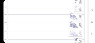
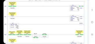
It looks like the contactor is controlled via timers rather then the pid in the program?
Can you explain why pid is not being used full and the timers energize the output to the contactor, could it gave been done with the output of the pid ?
 
Without having the full code to poke about in, I'd say there are two likely possibilities:

1. The PID loop does effectively control the "on time" of the heaters by virtue of adjusting the timer presets, or using N50:14/N50:2 to switch B3:13/0 on and off, or some other similar method. I have used this sort of approach before (although I'd like to think my finished code was somewhat less opaque) when I'm trying to control a temperature with a PID - you effectively have an on/off duty cycle for the heater output, and increasing your PID output increases the on time/decreases the off time.

2. Somebody tried to implement a PID-based temperature control loop, couldn't get it to work, threw in an undocumented fixed-rate on/off duty cycle, got it working by trial and error, and then called it a day.

If I had to take a bet, I'd bet on #2
 
Yes, it rather looks like they cobbled together a feedback loop using the Less Than instruction to turn on the heater.

Those timer branches are a bit baffling to me, though. It appears that the only thing controlling the heater is the B3:13 bit
 
The best way to control a digital output is by either Pulse Width Modulation (PWM) or Timed Proportional. I prefer the timed proportional option. There are several topics in this forum addressing this. Basically the PID output percentage is compared to a timer that resets itself. The output percentage is scaled to match the timer’s preset value. If the timer preset is 4 seconds (4000ms) and PID output is at 50% (2000), the digital output is on for 2 seconds and off for 2 seconds. If the PID output is 25%, the DO is on for 1 second and off for 3 and so on. To keep an output from cycling off/on too quickly when the percentage is very close to 0 or 100% , add a 1/2 second or more delay on the outputt
 
If you have a tech connect contract, the knowledgebase has examples of both time proportional and split range time proportional PID examples for RSLogix500. I have used them on extruders and seems to work well.
 

Similar Topics

Hello hai to everybody . my name is M.S.N.Rao. i am working as a plc programmer. i have some doubts regarding PID loops. if any one have...
Replies
1
Views
2,541
Hello, I have a motor that we are sending a RPM Speed Output from 0-100% to the VFD. However, the Motor HP needs to be limited to 6000 HP and the...
Replies
3
Views
83
I have S7 1512C controler for controlling 48 PID temperature loop, the output is PWM. Please I need the best, most efficient way to write the...
Replies
13
Views
586
Hi all, I'm having trouble solving a problem I've been working on for several months, and thought you might like a stab at it. The machine runs...
Replies
22
Views
920
How can I connect PID Output to a valve. In ladder logic program is there any logic do I want to add between valve and PID? PV=SP What will be the...
Replies
7
Views
406
Back
Top Bottom