Hydraulic control valves, symbols explanation

mikas_m

Member
Join Date
Feb 2007
Location
ck
Posts
154
Hello experts,

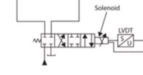
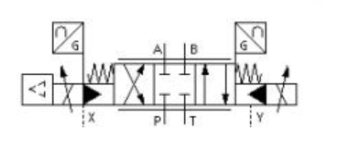
can you please help me understand the meaning of symbols shown in the attached pictures?
First is U/S (I guess U represents voltage, but S is for spool or spring or...?)
The second is U (upside down) and there is G.
Where can I find the explanations?

Thank you!

Symbol 1.png Symbol 2.png
 
this is the way I see it.

the first is a proportional valve with an lvdt feedback
double solenoid, blocked centered.
the return goes to tank.

the second one is new to me.
it looks like a double solenoid blocked centered valve, spring return to center.
then you have proportional controls on each side.
then there is the triangles which indicates manual over ride

i hope this helps, james
 
Hello guys and thank you for the explanations. Tom, I have found some webpages with pretty good explanations of the symbols of hydraulic valves, orifices, accumulators and similar. But what I couldn't find anywhere are those small square symbols. In the first picture it is written U/S in the square (below LVDT), and in the second is U/G.

symbols.png
 
Last edited:
The small square symbols are just a generic symbol for a transducer. Unfortunately, in this form there really isn't much of a standard, at least that I am aware of.

Generically, a transducer is simply a device that changes one physical quantity to another. Most often one of the physical quantities is electrical, although that isn't a requirement. Since there isn't much of a standard for these the language they were drawn in probably has a big effect on what the quantities are, since the letters are often the lead initial in the quantity being referenced.

For example, with the S/U case, you are probably correct that the U is voltage and the S is likely position. As James Mcquade said it is likely an LVDT but it could be any technology that converts position to voltage. It is also very likely that it is a "Feedback" transducer; that is, the physical quantity determines the electrical quantity. This is as opposed to a "driver" transducer, which would convert an electrical quantity into a physical quantity.

This is a completely wild guess, but it is possible that the orientation of the U is being used to indicate the direction of conversion. So in the S/U case it is a feedback transducer and in the U/G case it is a driver transducer. In that case the U/G things are just valve drivers. However, it is just as likely that the drawer mirrored the block and didn't correct the text.

I suggest you look at the blocks with the general idea of generic transducers and in the context of the larger schematic they are shown in. It may help you figure out what they are supposed to be.

Keith
 

Similar Topics

Hi, I have to design a panel using Delta PLC. I need to interface the PLC with a Hydraulic Proportional valve having the following specs. 24 V DC...
Replies
2
Views
2,026
Hello everyone, I'm reaching out for assistance regarding a project I'm currently working on. Specifically, it involves a hydraulic system with...
Replies
7
Views
400
Hi All, I could do with some advice on a hydraulic control system. It is necessary for me to accurately position a vertical hydraulic ram with...
Replies
34
Views
1,903
Hi, I am about to start a project controlling a hydraulic ram using a Siemens S7-1200 controller. It will need to be quite steady control, by...
Replies
1
Views
754
I want to share a trick and see if anyone can do better! With hydraulic presses there is a point at the beginning of the actuator movement when...
Replies
10
Views
3,914
Back
Top Bottom