Closed loop control of liquid through a Solenoid Valve

Batch is where you measure the volume produced, for example:
lets assume your flow meter gives 200 pulses per gallon and you want 50 gallons then 50 x 200 = 10,000 pulses. so in batching you want 50 gallons count the pulses from the flow meter until it reaches 10,000.
Most people scale the pulses so that the actual reading is in what ever measurement you want. Flow is where you measure the actual flow in say gallons per minute, obviously you would have to convert the flow pulses into actual gallons. Matching two fluids being blended in-line the best way is to control the flow for each i.e. water 10gal/minute lube 0.1gal/minute. But as you say you have little control over the flow rate and the fact you have pulse flow meters makes flow measurement a little more difficult.
To use PID to control the flow you will need to convert the pulses to flow per minute or what ever the time base is. on such a small amount this would be a bit of a challenge but possible, however, the smaller the sample for conversion the less accuracy you will have.
The best solution I can offer is that you manually set the flow rates with manual adjusted valves so in essence water flow is say 100 gals per 10 mins and lube is 1 gal per 10 minutes, then open both control valves, count the pulses when the lube gets to 1 gal, stop the flow, when the water gets to 99 gals close that valve.
At least you will have dosed the correct amount, however, depending on the settings of the manual valves you may not get a full mix at the end, so lets assume the flow is controllable enough to allow the water to get to 95 gals and the lube to 1 gal, close the lube valve & finish off with 4 gals of water.
Using flow instead of batch there could be considerable errors as when one of the flows increases or decreases the reaction time of the PID & mechanical properties of the valve could cause considerable errors, many systems use what they call bump less start on on initial starting a pre-set value is put into the PID control to set the proportional output to a fixed amount, the idea is that rather than the PID assuming no flow it would not ramp up to full output but a level that under normal will produce the correct flow rate, after a short time the PID is put into auto control so it is closer to the normal running conditions and can quickly control around smaller fluctuations.
One other thing you must consider is how fast these pulses are and the PLC you are using, some have a small amount of inputs that will react to fast pulses and possibly I/O interrupts to catch fast pulses, most PLC's will not be able to catch pulses from flow meters as the update time of normal I/O + scan time of the program is probably slower than the pulses. What PLC are you using ? Some do have high speed functions, however, some will require the addition of a counter module and these are not cheap.
Regarding the mixer I assume if this is what is commonly called SUDS Water/oil mix then the mixer is to homogenise the two dissimilar liquids.
On a lathe for example, an operator will make up his mix manually, put it in the sump & run it round creating the mix. I think because the machines you are feeding are probably some kind of automatic process they may not want unmixed lube to pass over the work piece & cutters. I'm no expert on machining so I think it would be a good idea to find out things like mix accuracy, could it be batched etc. It does look to me if this system is on standby until one or more of the machines calls for a top up, in this case without a buffer tank then flow control is best. I think you need a bit more information.

I have not selected a PLC yet, as I am waiting to satisfactorily clear these other instrument selections. I figured once I have this, I'd go for the PLC.

Yes this will be on standby, and used on demand for different machines. You got that right. And unmixed lube cannot be added to the sump as described.
 
If you went with the 1/4" (4200 pulse/litre) flow meter for coolant and the 1.25" (52 pulse/litre) flow meter for water, and if they pulsed at the same rate, then the mix rate would be 52/(52+4200) ~ 1.2% i.e. near th 1% target, although the water flow meter is way oversized and the client is spending an extra 20% or so on coolant wrt the 1% target.


Anyway, then the trick is to make them pulse at the same rate, but if you can do that you can probably also get them to pulse at some ratio of rates, so you don't need to oversize the water valve.


What controls the water flow rate (e.g. sump level bang-bang or sump level PID)? Does it vary?


What kind of valve flow characteristic (e.g. equal percentage)?

Water is gravity fed. There are two ways of feeding water though, one is through an overhead tank and the other through a pumping system from a centralized reservoir.

In either case, the liquid flow usually remains constant unless the liquid level in the tanks is too low. This does not happen too often.

I am thinking about a Dosing pump which will work on analog input to vary the stroke length in order to change the flow-rate to match that of the water which will be coming under gravity.

I am also open to achieve this via valves. I am just not quite sure how I can achieve this though. Yet.
 
Just had another look, you can also get a meter that gives a 4-20ma output so could be used in conjunction with the flow sensor to give a flow rate rather than a pulse. this takes away the need to calculate the flow rate in the PLC. Did not see this on the first glance. so yes, measure both, control one. providing it is set up correctly and nobody messes with your flow settings then it should work reasonably well even on varying flow rates of the water.

For some reason I had not seen these either. I'll have a look.

I didn't quite understand what you meant by measure both, control one. How do I control one flow-stream and achieve the right concentration?
 
From the diagram in the original post it looks to me like both of the valves are proportional valves. This should make things much easier regardless of how the flow requirement is determined.

I would come up with a system that is heavy on feed forwards and controllable in the water path. I would stick with volume ( pulses) and not try to convert to flow rate on the control side. As indicated already, the flow rate calculation will introduce a delay and process noise that you might not want to deal with.

You have a target ratio in mind. When you start dispensing I would open the valves to what should be the desired amount for each of them to produce the correct flow rate at that ratio. Apply scalars to the pulse feedback so the total scaled number of pulses is the same at the desired ratio. Then control the water path on the difference in pulses. This should result in better long-term stability as ANY volume error should be captured and ultimately corrected. As the flows deviates the total volume difference will be an integral of the flow error and will produce a much more stable error to control to.

Why choose the water path to control? As has been said, both systems are gravity fed and will suffer from flow rate changes based on that. However, assuming the diagram is at least somewhat representative and based on the OP saying the water feed if from the plant tank (presumably at a reasonably higher elevation) the water flow will be more consistent over time than the lube flow. This will make the correction much more linear over time as the lube flow is affected by gravity.

Keith

Well ideally I would have used two Proportional Valves. But sadly, including two Proportional valves along with two controllers is going beyond my budget.
 
no particular reason. I am still wondering what sets the overall flow rate: it could be manual; I suspect it is actually sump level, but whether it is bang-bang between high and low level switches, or PID to a setpoint, we do not yet know.


The other question is what is the volume of the sump (time constant = sump volume / flow)? The OP mentions a single CNC machine, so it might not be a huge sump. If the time constant is small, or if the sump level is bang-bang control, then I would not be as interested in ultimately correcting a period of high dosing with a period of low dosing, as I would be in always hitting the target dosing.

The flow-rate in the water line was after a manual check. This has the potential to vary from one client to the next. The water is fed either under gravity from an overhead tank or through a centralized pumping system that covers multiple water outlets throughout the entire plant.

The volume of the CNC Sump is approx. 400-500 Litres.
 
The OP stated that the cost is a bit high by having two control loops, assuming this is the case then having done similar systems (although with pumps & control valves). the simplest solution is leave the water as is & control the flow of the lube, with a bit of thought it should give reasonable responses and follow the flow of the water, assuming the water tank level is not going to change from full to half empty within a second or two it should be possible for the lube control valve to follow with ease. Again this is assuming the addon meter is used for 4-20ma, I would use this rather than try to convert the pulses into flow in the PLC. PI control should suffice for this application.
Caveats: If the flow of the lube is too small control may be a little difficult.
Assume there is no sudden change in flow rate (with gravity fed this should not be a problem). An empty line (tank empty) will require some alarm handling to stop the process in the event of empty tank or low flow.

Ive been thinking about this response of yours. The flow of lube for a top-up application actually is quite small, in the range of 500ml to 2000ml. The duration of dosing totally depends on the flow-rate of water.

I could try and control just the lube flow and have a simple ON-OFF solenoid for the water.
 
peristaltic Pumps do not fit well with flow meters due to the pulse function, however, the errors that may occur will probably be small. If both lines have flow meters then a batch system is the best, but I think the control of one leg but meter both is probably the most cost effective solution. Variable flow should not be a major problem providing the flow change is not too excessive. I think the trick is to try & adjust the average flow rates so that they finish around the same time (or better still the lube slightly in front of the water). If this is a cutting fluid then the tolerances do not have to be too accurate. Assuming a reasonable control can be achieved, the mix entering the sump of the CNC will mix in it's own right due to the turbulence and pumping of the lube through the system. I would hope the OP has been given a spec on accuracy, it would not be a good idea to take on a project without a specification.

OIL (Oil In Last). I cannot feed the lube before water. This causes what is called a 'Reverse Emulsion'.
 
When I talked about batching normally this would be add one ingredient then add another, however, that is normally consistent with vessels on load cells. as you have two flow meters then there is no reason why you cannot "Batch" both at the same time. Take this scenario:
Assuming the flow of the water in most cases is reasonably constant then on trial & error (probably could calculate it) if each flow meter gave 100 pulses per given volume then you would need to arrange the flow so that the water gave 100 pulses in x seconds & oil 1 pulse in x seconds. the idea is that by setting the valves or what ever controls the flow to a 100 to 1 ratio then they should finish together roughly at the same time. or to be a little on the safe side the oil should finish a little earlier. count the pulses until the values are reached i.e. 9900 for water (99 gallons) and 100 for oil (1 gallon). so you are batching in effect but simultaneously, the caveat is that if the flow is not very consistent then you could finish adding one ingredient before the other (probably not too important if the difference is small). The other solution is to try & use both pulse & flow the flowrate is controlled at a 100 to 1 ratio there are two ways to do this calculate the flow based on the time between each pulse or range of pulses to get the flow rate and also count the pulses so that the addition of each product is controlled in a way where you try to match the flow rate at 100-1 (or any ratio) and stop the flows when the pulse count = the required amount. This is not easy and may take some trial & error
But I still maintain the best way is to batch into a vessel & then mix but ideally the batch should be mixed in the tank by putting it through a high shear mixer back into the tank. Mayonnaise is often done this way so the other ingredients are added to the batch, blended and then the oil is added at a given rate to stop splitting.
 
I still don't see why you need to control the rate of the water...just measure it and feed that flow signal to a dosing pump. Use a solenoid to start and stop the water flow as needed to supply the sump and when stopped, the dosing pump signal will stop due to the flow signal stopping.
 
Yes as I said in an earlier post, leave the water just measure the pulses and dose the oil, however, to get a proper blend as there is no buffer it appears that the in-line blender goes strait to the machine so it will need to have some mix as it goes into the blender. I still believe that manually control the water flow at a given rate and dosing the oil is the best way to go the meters chosen are pulse & depending on his PLC it would be possible to convert the pulse to some kind of flowrate but using flow rate rather than pulse to dose a known quantity is not ideal. The flow meters chosen also have an add on meter to convert it into flow rate this is another possibility. To be honest this looks like one of those projects that has not been thought through there should be a design spec and built around that.
It needs a bit of thought, I once was given the job of dosing a chemical into a water base (in-line), the sensor & electronics for that particular chemical was very expensive and a 12 week lead time as they were built to order, I experimented with a conductivity meter and realised that at the given temperature of the water I could read a concentration of the dosed chemical although it did not conform to the known measurement however, it was consistent & linear so we used a spare conductivity meter, using our Hygiene testing equipment to compare the concentration we were able to calibrate it and it worked well.
 
To be honest this looks like one of those projects that has not been thought through there should be a design spec and built around that.
It needs a bit of thought, I once was given the job of dosing a chemical into a water base (in-line), the sensor & electronics for that particular chemical was very expensive and a 12 week lead time as they were built to order, I experimented with a conductivity meter and realised that at the given temperature of the water I could read a concentration of the dosed chemical although it did not conform to the known measurement however, it was consistent & linear so we used a spare conductivity meter, using our Hygiene testing equipment to compare the concentration we were able to calibrate it and it worked well.

Yes this is a project I am working on for the first time. I aim to design a prototype and test it on my own CNCs and modify it as per the outcome of trials.

Off-Topic:-
Measuring the concentration of the make-up liquid is something I intend to add at a later stage. Why would you choose conductivity over Refractive Index for measuring concentration?
 
To answer the first question, Conductivity is not what you would normally use, however, due to the long lead time & cost we conducted experiments and found the conductivity to vary according to the concentration. although the range was small we could control it quite easy. as you may know conductivity will vary with temperature that's why the probe has a temperature sensor to compensate. we found that we could control the dosing within acceptable parameters, however, this did take some time on trial & error. You talk about PWM but state you are using an analogue output PWM is not analogue. it is Pulse Width Modulation. so if you are using analogue you need a valve that will open from 0-100% on a 4-20ma or 0-10v signal. in theory the valve will open proportionally to the given signal although may not be truly linear. purists here will start to go on about compensation of the non linear curve but in reality if the feedback (assume flow rate) into a PID will attempt to modulate the valve to compensate for given set point versus the feedback. so calibration is the flowrate rather than the valve.
Ideally the flow rate you require should be in the middle band of the valve position that way you more control over the process.
Again some years ago I did a system that blended water & tomato paste in-line at a ratio of 60/40 so essentially the same process as yours. although the batch weight was measured on load cells in the vessels, the blend was controlled by the two pumps. both pumps were controlled via PID control from flow meters, At start up, the PID controllers were forced to manual for example 60% & 40% of output for a short time to allow the flows to stabilise, the controller PID's was then switched over to auto, this gave very good control over the blend. (note: it was not actually 60/40 but by trialling we found the valve position that gave the rough flow required). It was a little more complicated as the batch weight was set below normal, a sample taken & tested using a refractometer, then the values put into the HMI and the additional blend adjusted to correct any error. so 1500kg of blend was added to the tank, brix readings added to process, batch in the other 500kg at a blend compensated by the calculations.
 
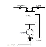
This is the way I would do it. See Very rough diagram.
Set flow counters to zero, open both water & oil valves dose in fluids until set points reached.
In the mean time when a small level in tank, divert valve back to tank & run blender. Continue blending back into tank until mix is well blended, when batch required, open divert to sump & discharge.

Batch Blender.png
 
You talk about PWM but state you are using an analogue output PWM is not analogue. it is Pulse Width Modulation. so if you are using analogue you need a valve that will open from 0-100% on a 4-20ma or 0-10v signal. in theory the valve will open proportionally to the given signal although may not be truly linear.

Yes I meant using a PWM Controller which accepts Analog outputs from a PLC and sends PWM signals to the Valve.
 

Similar Topics

So it looks like i am stuck with an old reliance DC drive on this project instead of the powerflex dc w/ 22-COMM-E. That being said i am trying to...
Replies
0
Views
1,188
I have just received a RFQ for a closed loop pumping system (hydroforming ). I did a small system like this about 8 years ago in a SLC. It worked...
Replies
3
Views
2,303
Is it possible to operate a unidrive sp in closed loop vector contol to drive a roller that is turning in a cradle type configuration and the...
Replies
2
Views
1,999
Hey guys, Im not sure how appropriate this is for this forum but I have received alot of help from you guys in the past. Im taking industrial...
Replies
4
Views
2,162
HI, i am trying to control DC motor and encoder,by using plc200.cpu222 HSC 0,and analog output card. can you help me by giving me a hint about the...
Replies
2
Views
1,956
Back
Top Bottom