Hi folks,
testsubject,
Apologies, I did not see your last query originally so I'll just quickly address that first...
testsubject said:
George,
Thank you for your detailed explanation. It was very informative.
Where did Dave get the information stated in the quote? I am looking through 520-um001.pdf and cannot find this paragraph.
The particular text I provided was from a Rockwell Automation document titled:
Introduction to Functional Safety
Focus: ISO 13849-1
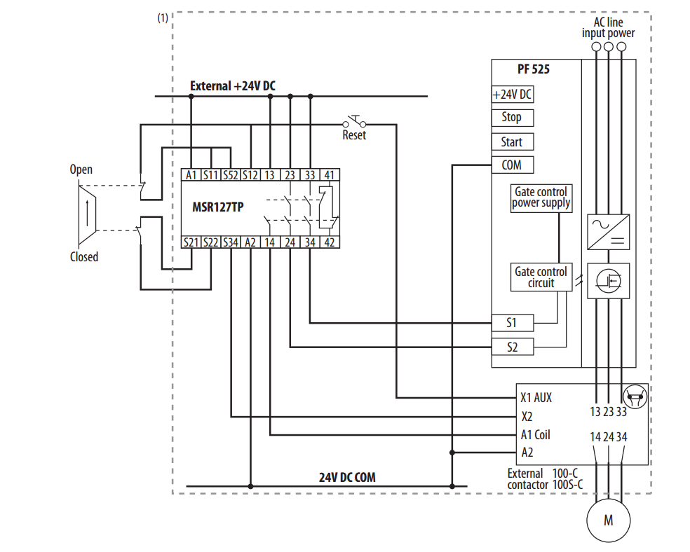
On page 21 of that presentation is the PowerFlex 525 STO example I was referring to. I can't seem to find a link to this document online but I do still have a local copy. Unfortunately, we are not permitted by the Forum to link to or attach manufacturer documents other than from official sources. If you would like a copy please PM me.
Dave Rasmussen was not "getting" that information from somewhere else, as such. He wrote it himself using his expert interpretation of relevant standards, such as ISO 13849-1, and his knowledge and experience on the Rockwell components being used. He "is" the information, if you will. He was Rockwell Automation's "North America Safety Manager" at the time. You would not have found much higher regarded information on the subject elsewhere. Dave has since moved on to Amazon, however, but he is still very much involved in Functional Safety and in particular, Rockwell Automation products.
jrsnydley,
jrsnydley said:
...The monitoring circuit for the safety relay is daisy chained through Relay Output 2 (NC) of the drives. The parameter for the relay output (81) is set to MotorRunning. We are having issues where the NC relay is stuck open...This equipment has only been in the plant for a year and we have replaced two of these drives for this reason already...
Standard best practice for STO monitoring on these drives, using their relay outputs, is to monitor the STO status and not the running status. Firstly, it is the correct status to monitor, and secondly, your issue of drives failing prematurely. If you have each Relay Out2 (t081) set to 2 "MotorRunning", then each time the drive is started or stopped the relay contacts are switching. This is usually a much higher frequency than if using the setting 29 "Safe-Off", which would only switch the contacts when the safety function is executed. This is arguably less frequent in most applications (unless you've got those "E-Stop & Go" type Operators). It also matters, of course, what type of load you are switching through the contacts. Regardless, I always use a suitable interposing relay on these outputs to protect them from potentially dirty loads. From a distance, your t081 setting would be my best guess as to why these drives have failed prematurely.
So it's possible that the simplest solution "may" be to reparametrize t081 to 29 "Safe-Off" instead and save the contacts, at least for a longer period of time? Just be aware of the potential for different settings to t081 meaning the normal state of the contact may be open or closed. This can affect your current circuit logic. There is also the adjacent STO setting for t081 of 30 "SafeTqPermit" which is the reverse logic.
jrsnydley said:
...Can this monitoring be eliminated? Is it safe to assume that if the safety relay is not reset, the STO is not energized and the drive could not be running?
A saying of mine...
It is safe to assume that to assume is unsafe.
The common reason for output element (drive) monitoring is to further ensure that the safety function executed and the safe state for the application has been achieved. This measure falls under "Well Tried Safety Principles". If the safety relay has been tripped, and you have no feedback from the drive to acknowledge that the output element has actually opened, then it would "normally" not be safe to assume that the drive has indeed powered off its motor. By removing the output element monitoring, you are increasing the fault tolerance level for the safety function and decreasing the Diagnostic Coverage (DC). If existing output element monitoring was "required" (Risk Assessment), say for Category 3 minimum (SIL2/PLd), then the use of practicable measures of detecting a single fault should be applied. In such a case, you would, of course, not be advised removing the monitoring, but instead retaining it using one measure or another. The "another" here being the topic of this thread.
Remember, once you require Cat 3 (SIL2/PLd) or higher you must use any reasonably practicable measures of detecting single faults. Output element monitoring is one such measure.
This is why "monitored" redundancy is important at certain safety levels. One output element may have failed dangerous (contactor welded) but the other will maintain the safety function when called upon. Here, the healthy contactor continuing to operate will mask its partner's fault. A situation could potentially arise where eventually the second contactor fails dangerously (welds in) and now you have lost the safety function and cannot execute the safe state when called upon. All going undetected. This is not satisfactory for Cat 3 (SIL2/PLd), or higher.
Also, notice a distinct difference here. For a dual contactor output element architecture, both contactors will have separate mechanically linked contacts for monitoring. This is dual redundancy with dual fault detection. Using this measure will in most cases give you a Diagnostic Coverage of 99% for the contactors.
In the case of a drive using STO, such as the PowerFlex 525, and again considering Cat 3 (SIL2/PLd), the STO monitoring via relay is single contact monitoring. This is acceptable as reasonably practicable as the STO feature has built-in diagnostics to detect internal faults on the STO channels. Either or both failing the test will trigger the relay output, once configured to monitor the STO status. The option is, as we've covered, also available to monitor the STO status over Ethernet/IP communications, and is deemed equally control reliable for this level of safety. If needing to achieve Cat 4 (SIL3/PLe) for this family of drive, you may add a safety contactor in series as an additional output element and direct monitor its mechanically linked contacts. This again will allow you achieve a DC=99% for these drive applications.
Hopefully the simple parameter change above would suffice here for you. But if not, you would first have to know whether or not monitoring was/is necessary here before deciding if you could remove it entirely i.e. is Cat 3 (SIL2/PLd) minimum required? If you don't want to get into all that or you don't have info to hand, then I would recommend you leave the monitoring in place in one form or another.
If you do decide to monitor over comms, remember to monitor the value of "Digit 5 SafetyActive" in parameter b006 and not "Digit 1 Running".
Regards,
George