Data style troubles

PLC Pie Guy

Member
Join Date
Jun 2013
Location
Halifax
Posts
1,144
Hey All.
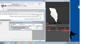
I'm working on an IFM Vision system. Its interfaced with an L45 and seems to do well. However, if you look at the screen shot you will see what my trouble is. The sensor is always sending me back 2 HEX values as SINT data types. The CPT instruction in the image works, 60% of the time. If you notice in the image, the value of [14] is "bd", which should be = 189. So why does my CPT instruction end up negative 66 if [15] = 0 and [14] = 189. it should be simply 189 since its multiplying [15] by 0. Normally that is the case, but every few minutes this value will do something like you see on the screen and end up with -66 or something else that does not equal what I have as an expression in the CPT instruction........ I'm totally lost on how it comes up with this value.... The works thing is, this works, and its accurate, then its wacky, then it works again.

Help please!!!
Untitled_1.jpg
 
So, the longest RA Tech call Iv ever had just ended with no success. Two of their heads on this all afternoon and still stuck. They want to try again tomorrow. They tried a few things with Byte swaps and such but no love. IFM...... No thanks from the absolute 0 support I received today from IFM (n)(n)(n)(n)(n) to you.
 
The HEX Value "bd" = -67 because it is a signed integer value. The 8th bit is true which makes it negative.
Hexvalue1.jpg

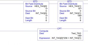
If you use the BTD instruction To copy the bit pattern to and INT then you'll get 189. This will allow you to use all 8 bits without the signed bit.
BTD HEX To INT.jpg
 
You can do this in one step, too, and write directly to your INT tag by setting the Dest Bit in the left BTD instruction to "8" rather than "0".

I use this method frequently when sending Group IO to a Fanuc Robot. The Fanuc I/O registers in the PLC are all defined as SINTs so, in order to send an INT value to the robot, use two BTD instructions to do it.

BTD.jpg
 
Steve,
I have used the same method to swap bytes but in this case that would not give you the correct value. The first value needs to be multiplied by 256 then add the 2nd value to get a total. Then convert that total to a Real. The compute instruction is used to apply an offset need for the device. (1st value *256 + 2nd value) To convert to real I would have used the DIV by 1000 and store results in a Real Tag. (0.189) I believe this is the intended result the OP was looking for. The Manufacturer recommended changing values coming from the device to strings and CONCAT to get results then STOR instruction. (string to real) I believe he went that route instead.

http://www.plctalk.net/qanda/showthread.php?t=113068
 
cwal61 - I believe the BTD method I describe works exactly the same as your method describes and will give the correct value. If I'm wrong, I would appreciate an example.
 
My apologies, I overlooked the fact that the 8th bit is 256. So I stand corrected.
 
Last edited:

Similar Topics

Hi guys have only just been getting stuck into learning about PLC’s. I’ve got an older version of Studio 5000 and a CompactLogix PLC. I have...
Replies
2
Views
476
I have recovered 4 data carts for a PLC-2. The program that I have is pretty much useless (Ladder only no descriptors 712 rungs) THANKS JOHN...
Replies
2
Views
4,043
Has anyone migrated Proficy Historian data to a new server? I followed the guide to move all the data over, but when I run the utility, it stops...
Replies
0
Views
35
I cannot add SLC500 analog input tag (I: 8.3) to EZSeries Touch Panel Editor (V 5.3). I used all the listed tag datatype but it all says "Invalid...
Replies
8
Views
173
Hi, Wy we log data in PLC using DLG instruction, when we have option to log data in HMI
Replies
1
Views
72
Back
Top Bottom