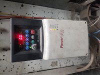
Studio5000/powerflex 40

hutch1980

Member
Join Date
Jun 2020
Location
california
Posts
13
Recently started working a side job at a recycling plant and have been asked to go through some of the drives that the operators are currently controlling by potentiometer on the drive. I know I need to change parameter PO38 speed reference back to 5 for "comm port". The A103 com data rate I'm assuming I can get off of one of the other drives on the network but I'm not sure how to find the A104 comm node address. I'm thinking the drive was changed at some point and the parameters weren't set up right for the communication. There's a two conductor cable hooked up to the RS485/DSI port on the drive. They are using a digital input to start the drive so I think they just use the comm port for a speed reference from a rsview project. I'm not real familiar with studio 5000 so wasn't sure if I could find the node address in there some where or not. I'm assuming that it was controlled at one point from the rsview project since there is a box to change the speeds on there. Any tips or advice would be greatly appreciated!
 
Follow that 2-wire cable to wherever it leads.

In general, you only want to select "Comm Port" if there's something periodically writing the Control word and the Reference word to the drive, more frequently than the timeout.

Doing direct RSView or other HMI control of the drive speed probably wouldn't do a cyclic command like that. Instead, they would do an on-demand change to a Preset Speed parameter, and the drive would be set to run at the Preset Speed.

I agree that when you find where that cable goes, you can infer the drive's Node Number from whatever is controlling it. If there is no daisy-chain or hub/spoke connection of that RS485 connection to other drives, then there is no reason for the drive to by anything but Node 1.
 
Thanks for the quick response Ken. I'll trace back the cable when I get back to the plant this afternoon. It could be just being told to run at a few different preset speeds though the communication. I had read up about it being daisy chained but that specific drive just has the one cable. They basically only run the drive at 35hz 90% of the time. Every once in a while they speed it up to 45hz if the line is running good. I just want to keep the operators out of the panel. They said they used to be able to control it from the RSview screen but I can't verify if it ever even worked because it was before I started working there. Worse case scenario I can mount a speed pot outside the cabinet. I'll trace the cable out this after noon and let you know what I find. Thanks again for the info.
 
So I traced the cable out from the port on the drive. it actually does go down to another drive communication port. that drive had a terminating resister across the terminals even though it was wasn't the last drive in the circuit. I checked that drive and the speed reference is set to the drive pot also. There are 3 or four other drives in the buckets in this room and every one I checked, the speed reference is set to drive pot on all of them. I was told that some of those are controlled through the screen. There is a spot on the screen to adjust the hz going to most of them but every drive was set up for speed reference from the drive pot. Looks like the whole network for the drives isn't functioning so I would have to get that back up before they work from the controller.
 
Thanks for the followup !

If you can, figure out how exactly that RSView field connects to the PLC controller or the drives.

PowerFlex 40's are often set up in "multi drive mode" where one EtherNet/IP or DeviceNet adapter has a sub-network of RS485 wired drives.

Or, that RS485 pair might go back to a standalone network module or even a serial port on an HMI computer.

This is very probably a situation where the previous engineer encountered some problems, so they dropped back and set up the drives to run from local potentiometers.

Unrelated Anecdata: I was updating a set of controllers last night with very clear IP addresses on printed labels on the front of the controller. Turns out two of them were swapped. Protip: label the Ethernet cable, the cabinet or the mounting panel, not the CPU, network module, or power supply.
 
Ken, I'll be back at that plant later this afternoon and see if I can find where the drives communications cable originates from. I'll also take a look at the computer that's running the rsview software and see how that's tied in. Thanks for all of the info. It definitely seems like they all worked from the software at some point because the option is on the rsview project. when they double click the motor a box comes up where you can set the hz then hit enter. Operator said that there was only two not working so I'm assuming since he can enter a new speed from the rsview project he believes they all work but that doesn't seem to be the case. I think your correct in that they had problems some where in the past and the drives ended up being set up for local speed reference. I've never really dealt with having all the drives on a network before so wasn't sure how to proceed. The other places I've worked all use digital I/O's and an analog output from the PLC for the speed reference. Always fun working on new things though.
 
Ken, thanks for the help. The owner of the company was there last night and I explained what I've found so far. He gave me the phone number of the guy that originally set up the network so I'm going to give him a call today and see what documentation he still has and how everything was working when he left. I need the plant down to safely trace the cables from the DSI ports of each drive so I can draw out exactly how everything is wired up. I'm hoping he also has documentation on the node addresses for each drive since I now know there are multiple drives tied together though the DSI ports. I'll let you know what I'm able to find out. I believe the plant is down Saturday so that will give me enough time to go through everything and see exactly how the comm. cables are all ran.
 
Sorry, didn't get back to you what I had found. Had other issues and didn't get back to the tracing of the cables going to the DSI ports. There are 5 drives total that are connected with cables from each DSI port. The 2nd powerflex 40 drive from the end has a ethernet adapter module on the drive with an ethernet cable going back to a switch in the PLC cabinet. I believe this is the "multi drive mode" that you were speaking of Ken? If I understood you correctly, the drive with the ethernet cable is the one connected to the PLC and then is sends information through the DSI ports to the other 4 drives? So step one for me is getting that drive to communicate with the plc? The switch is a Hirschmann RS2-TX. I noticed that port 7 doesn't seem to be communicating even though there's a cable there. I'm going to try and trace out the ethernet cable from the drive to be sure which port it's going to. I also have a fault light on the switch that I still need to investigate.
 
It sounds like you're doing a good and careful job examining the control system.

Yes, one drive with a 22-COMM-E under the "maternity dress" cover with a daisy-chained RS485 cable going to four other drives is a standard Multi-Drive setup.

Check out Chapter 7 of the 22-COMM-E user manual for diagrams and wiring and more important information:

https://literature.rockwellautomation.com/idc/groups/literature/documents/um/22comm-um004_-en-p.pdf

Get your hands on the Studio 5000 *.ACD program and you can figure out quickly if the drive that hosts that 22-COMM-E is set up for Single Drive or Mult-Drive mode.
 
I have a copy of the program and it looks like the CV3 drive that has the ethernet adapter is writing everything to Drive_grind1. When I go to my IO tree under ethernet I think its the ETHERNET-MODULE GRIND. I'll have to compare the IP address on the CV3 drive to see if it's set to what I'm showing on that module in the program. If that hasn't been changed already and not set up correctly. Is there a quicker way to know for sure which of these in my IO tree is set up for a certain drive? Thanks for the help Ken.
 
Last edited:
also thanks for the manual. I was reading through that and plan on going through the setting today when I get back to the plant this afternoon.
 
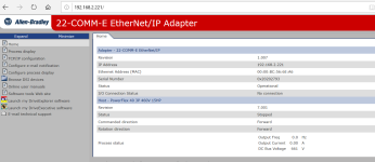
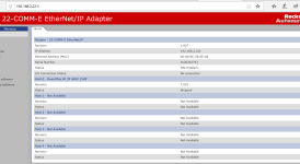
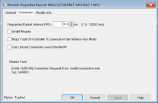
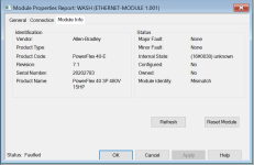
Been a while but just wanted to update since the plant shut down I was able to play with this a little more. The ethernet adapter that the drive is hooked to is called CV3. the port light on this ethernet adapter is always blinking red and the switches on the back of the adapter are set to multi drive and web page enabled. i unplugged the ethernet cable going into the ethernet adapter and plugged into my laptop and was able to ping the PLC ok so i know the cable going back is good. plugged cable back into the adapter. powered the drive down and set the switch on the ethernet adapter to single drive mode. powered back up and then i had a green light for my port light. i'm not able to view any settings through the hmi on the drive because this is an older drive and doesn't have that feature. i was able to plug into the switch at the plc and pull up the web page for the ethernet adapter. i've included a picture of when i pulled the page up in single drive mode and one of multidrive mode. in multidrive mode under "status" i had "dsi problem". flipping the switch to single and going back online that fault went away but under I/O connection status i still had no connection. I also included two screen shots of the plc when i'm online trying to connect to the ethernet module. one shows a mismatch fault and the other shows an invalid connection size. I'm going to research those codes tonight to see if I can find anything but any other advice would also be greatly appreciated. Thanks again.

single drive mode.PNG multi drive mode.PNG ethernet adapter.PNG ethernet adapter_1.PNG
 
Excellent and useful information !

Your system looks like it's fairly old, in part because it appears to be using a "Generic Ethernet Module" object to control the 22-COMM-E module instead of an actual drive profile for a PowerFlex 40.

Because your 22-COMM-E is set up for multi-drive mode with the DIP switch, the Generic Ethernet Module object size in RSLogix 5000 is larger (for 5 drives) than it would be for single-drive mode. So it's not surprising that you get an indication of a size mismatch for the logical connection when you change the DIP switch to single-drive mode.

When you're in multi-drive mode, there's evidently something wrong with the wiring or the configuration.

To get this system working in multi-drive mode, you need to know which physical drive correlates with which set of tags in the Generic Ethernet Module. The drive that hosts the 22-COMM-E is always Drive 0, but you need to figure out which drives are Drive 1,2,3,4.

The order they are connected doesn't matter, and it sounds like you can't easily look at the parameters inside them.

It's possible they are set up as the designer intended. It's equally possible they are all set for Drive 1, or some other un-desired setting.

What sort of HMI do you have on this PowerFlex 40 ? Does it not allow any parameter access at all ?

I haven't used the good old 1203-USB interface lately. I suppose you might be able to fudge around with an RS485 / Modbus connection if you wished, to try to figure out the DSI node numbers.
 
ken, once again thank you for the quick response. The drive has the standard built in HMI and i can view the drive parameters through the hmi on the drive but can't see any of the parameters of the ethernet interface. The operators at the plant say everything used to work from the hmi but I can't confirm that. Since I've been there they have been using the speed control from the local speed pot on the drive. I wired in the remote pots on the cabinet just to keep them from opening up the bucket all the time. From going through the manuals it looks like i should have the ethernet cable going to the main drive with a 120 ohm resistor on the dsi port then the dsi port daisy chained from one drive to another with another resistor on the last drive. the way the dsi ports are wired the main drive is in the middle of the dsi loop. they have a resistor on my main drive and then the dsi loop splits and goes each direction and they only have a terminating resistor on one side. I'll do a quick sketch tomorrow morning of the dsi wiring from drive to drive. not sure if this is what is creating my issues or not.
Not sure if i mentioned this earlier but when i checked the node address on all the drives besides the main, they are all set to 100 which is default from what I read. I thought in the manual it said the node address had to be different on each drive in the dsi network. I'm assuming the drives were changed over time and whoever changed them didn't know what parameters to change to get them working on the dsi network.

powerflex 40.jpg
 
You're decorating early for Halloween, I see. :)

RS-485 daisy-chains are generally not sensitive to the order or location of the addressed devices; the "master" doesn't have to be at the end, or at the place with the termination resistor.

The diagram on page 7-3 of the 22-COMM-E User Manual shows the drive at the left side of the daisy chain, with a termination resistor installed, but it can definitely be at any place along the daisy chain.

On the 22-COMM-E itself, the default settings (parameters 22-28) for drives 0,1,2,3,4 having Modbus Addresses / Node Addresses of 100, 101, 102, 103, 104 should still be in place.

And then on each PowerFlex drive, parameter A104 should be 100, 101, 102, 103, 104 for the drives numbered "Drive 0,1,2,3,4" in Multi-Drive Mode.

Again, the drive where the 22-COMM-E is installed is "Drive 0" for the purposes of Multi-Drive Mode, but it has the A104 = 100 Node Address.

You might find a confusing table of addresses on Pages 7-6 and 7-7 of the User Manual, where they have an example program. In that example, the drives are addressed 1,2,3,4,5 instead of 100, 101, 102, 103, 104. But the defaults are correct as shown on page B-5.
 

Similar Topics

Just purchased Studio5000 and have it installed, will be connecting to 3 brand new Powerflex 7000 VFDs. In setting up the module, how can I tell...
Replies
7
Views
757
I have two of the same PCs and one can connect to my drives through the studio 5000 v34 program and the other PC can not gets the Error posted in...
Replies
7
Views
953
I have an array of 55 REAL values. Is there a way to multiply based on the array location ? I have 55 transfer belts that are equally spaced...
Replies
3
Views
149
Hi Hope you all are doing well. Iam working on a project with some AOI. I also hate no online edits... lol. My problem occurs when I use a UDT...
Replies
2
Views
157
I am not sure if this is possible but if there is a way, you guys would be the ones to know. I am currently working on a project where we are...
Replies
7
Views
215
Back
Top Bottom