You are using an out of date browser. It may not display this or other websites correctly.
You should upgrade or use an alternative browser.
You should upgrade or use an alternative browser.
Function Call in TIA and Simatic Manager like in AB's JSR
- Thread starter IdealDan
- Start date
L D[AR2P#0.0]
Lifetime Supporting Member
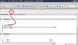
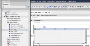
In TIA/simatic manager insert an empty box and type in FC + number.
Really, Insert an emty box in OB1 right?In TIA/simatic manager insert an empty box and type in FC + number.
1. What is the difference between FC and FB?
2. Finally, How can I simulate Analog value please?
I'm really grateful
Regards
L D[AR2P#0.0]
Lifetime Supporting Member
FC has access to parameters and temporary data. The temporary data is not "remembered" between scans.
FB has access to parameters, temporary data (as FC) and static data which is remembered between scans. Parameters and static data are stored in data blocks.
wrt to simulating analogue values, which platform (TIA or Classic) and CPU are you using?
FB has access to parameters, temporary data (as FC) and static data which is remembered between scans. Parameters and static data are stored in data blocks.
wrt to simulating analogue values, which platform (TIA or Classic) and CPU are you using?
L D[AR2P#0.0]
Lifetime Supporting Member
L D[AR2P#0.0]
Lifetime Supporting Member
I can't thank you enough bro.FC has access to parameters and temporary data. The temporary data is not "remembered" between scans.
FB has access to parameters, temporary data (as FC) and static data which is remembered between scans. Parameters and static data are stored in data blocks.
wrt to simulating analogue values, which platform (TIA or Classic) and CPU are you using?
I really Appreciate.
Also, sorry for my late response please, I was out and now back.
For the Analog Simulation, I meant TIA with S7-300 PLC Please.
L D[AR2P#0.0]
Lifetime Supporting Member
It all depends where you have addressed the analogue input and where the program is running. Will the program be running in a real CPU or PLCSIM - and which CPU model?
plcsimit all depends where you have addressed the analogue input and where the program is running. Will the program be running in a real cpu or plcsim - and which cpu model?
L D[AR2P#0.0]
Lifetime Supporting Member
If the analogue input is addressed in the process image, you can write to the image to simulate the analogue input.
e.g.
e.g.
Code:
L MySimulatedValue
T IW200


L IW200 //read analogue input and scale etcL D[AR2P#0.0]
Lifetime Supporting Member
Please forgive me,If the analogue input is addressed in the process image, you can write to the image to simulate the analogue input.
e.g.
Code:L MySimulatedValue T IW200 L IW200 //read analogue input and scale etc
Could you please clarify a little more?
I was thinking some thing like slide on PLCSIM and also move command
I'm lost. Please help more.
Regards
L D[AR2P#0.0]
Lifetime Supporting Member
Yes you could use the slide using PLCSIM - I was assuming you were going to write some code to simulate a process hence the need to simulate the analogue input.
Oh, please how can I simulate with slideYes you could use the slide using PLCSIM - I was assuming you were going to write some code to simulate a process hence the need to simulate the analogue input.
Similar Topics
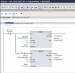
I created this FC and it compiles, but when I use it in my MAIN OB1, it appears to have two outputs. See pictures.
What am I doing wrong here...
- Replies
- 9
- Views
- 1,467
Hiya - another TIA question
I've a got a sequencer that on step 80 should run another function (blank search)
The way I Run and Stop this...
- Replies
- 18
- Views
- 4,427
Hi, I'm learning GX Works 2 for upcoming project. I want to use ST Function Blocks in Ladder Program and it works if the FB(Structured text)...
- Replies
- 5
- Views
- 1,651
I'm struggling to implement the test case which is highlighted. What ends up happening is the servo starts when I turn the cycle on, but it...
- Replies
- 3
- Views
- 1,062
Hi all :) ,
I'm very new to CitectSCADA and Cicode programming, however have good programming experience in most major programming languages...
- Replies
- 0
- Views
- 1,246


