Transit Timer for Motor-driven switches

RMA

Member
Join Date
Sep 2004
Location
North of Hamburg, Germany
Posts
2,052
This is almost too embarrassing to ask, but I've been puzzling with this on and off for a couple of weeks now and I can't think of an elegant solution.

I've used the standard solution for monitoring the start up of motors (it also works for valves with only one feedback signal) often enough i.e.:

U #Motor
L #Response_Time
SE #Timer_Nr
UN # Motor
R #Timer_Nr
U #Timer_Nr
UN #Response
S # Fault
R #Motor

My problem is, how do I adapt this to motor driven switches where the PLC Output is a pulse to start the switch moving in one or the other direction, but there is no feedback signal from the switch motor to say that it's running. The same would apply to motor driven valves with two feedback signals.

The only thing I could come up with was handling the Open and Close commands separately and watching for the other command coming up in between and then also resetting the timer if the appropriate feedback signal came before the timer timed out. It works but does look messy.

This is an every day problem, somebody out there must have an elegant solution!
 
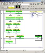
Don't know if this is of any help, but I handle the dual valve feed back like this. All of the following are inputs to a fault timer, if commanded to open and not open, if commanded to close and not closed, if both feedbacks, if neither feedback.

valve.jpg
 
he PLC Output is a pulse to start the switch moving in one or the other direction, but there is no feedback signal from the switch motor to say that it's running.

If I understand it correctly, your problem is that the motor starts with a pulse (from that I take that it needs another pulse to turn off). And you feel unsure about the whole thing because there is no feedback from the motor - only from the valve when it has reached one of its final positions.

Like Ken suggests, I would monitor the following:
1. That the valve leaves the closed position T1 time after the motor starts towards the open position.
2. That the valve reaches the open position T2 time after the motor starts towards the open position.
3. That the valve leaves the open position T1 time after the motor starts towards the closed position.
4. That the valve reaches the closed position T2 time after the motor starts towards the closed position.

It doesnt have to be elegant, it just have to work ;)

I would also investigate the possibility to get feedback signals from the motorstarter.
 
It doesnt have to be elegant, it just have to work

This true, but you get to point sometimes where it just looks too much like a cludge.

Perhaps the answer to do it in ladder like Ken does, somehow it looks better that way than in STL/IL.

That's a job for next week though as I'm off for the weekend now.

Have a good weekend one and all.
 
....but there is no feedback signal from the switch motor to say that it's running....

If there is NO feedback, you can't have an alarm. There's nothing to compare the theoretical state of the motor to.

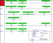
If there is feedback from the motor, but you are simply no longer driving the output, then simply create a pseudo-motor starter circuit, like so:

[attachment]

The outputs START_MOTOR and STOP_MOTOR are "pulses", only doing their job for the time it takes the motor to respond. But the "Pseudo_Motor_Run" tracks whether or not the PLC "thinks" the motor should be running.

plcs.net.jpg
 
Last edited:
We had a similar application on a control replacement. We scrapped the motorized switch first thing, and let the PLC timers emulate the switch. Thats all the switch was for, after all--a slow timer. It had a shaft with adjustable cams to change the timing.
 
Funny what you think of lying in bed at 4:00 in the morning!

I realised that Allen's elegant solution wouldn't work for me and came up with the idea of using a pair of Stats to signal "Valve should be open" and "Valve should be closed". These could then be edge-triggered by the Open / Close Outputs and take the place of the commadx in Allen's ladder. In effect, I think it's more or less the same as Allen's second post.

That should work OK, just need to think about the implications of what happens on Power or DP-Comms failure.

John,

These switches are not motorised for timer delay effect, they are switching up to 60,000 Amps, are 120 cm long x 50 cm wide and 80 cm high when the contacts are open. You can't switch things like that with a solenoid coil! :D
 
Satisfy my curiosity

OK I am curious - I learn more neat things this way.

The last time I saw a 60 K amp load was in a steel mill electric furnace (480 V 3 phase for carbon electrodes).

What is your load??

Why is switch operating time important to you??

Dan Bentler
 
Why is switch operating time important to you??

Purely to check that we don't wait forever in the case of a fault before noticing that something has gone wrong. The switch travel time is a little over 5 secs, so I want to start a delay of 6 (or maybe 7, if there turns out to be a wide spread in switching times) seconds and then look to see if the switches are in the desired positions.

These are the output switches connecting the outputs of 21 Modules of a capacitor bank system to common collector rails. Each module has a capacity of 1.44 or 2.88 MJ at 24 kV for a total of 49 MJ. When you dump the lot at once into the four magnetic coils the customer is hoping to generate a magnetic field of between 40 and 100 Tesla for between 2 secs and about 10 ms - it'll make quite a bang - especially the first few times when we expect they'll spend the rest of the day sweeping up the remains of the coils!

The maximum current in one coil will be about 340 kA, the modules ( and the switches have to survive the max. short circuit current of about 43 kA.

The switches are actually intended for switching 60 kA AC under load at power distribution centres and the like. We won't be switching under load because it's DC, but the mechanical stress will still be pretty hefty.
 
Alternative way to control/monitor this application

To all:
If you are truely looking for an elegant solution...
Has anyone ever heard of a product from Siemens called SIMOCODE pro. It can handle all the logic this application requires without a PLC and can provide the overload protection for the motor as well.

I can tell you more if you are interested but don't want to come off sounding like an advertisement.

John Burns (burnjj)
 

Similar Topics

I have some logic that I have written within a 5380 series controller that tracks the time an event is started, while the event is running an RTO...
Replies
2
Views
91
Hi all, I have a simple question that I have overcomplicated and gotten stuck on. I have a variable, we can call it "light" that I need to stay...
Replies
4
Views
310
Question to anyone with ideas about my thoughts on upgrading a very vintage timer, which is being used to switch between 2 5hp domestic water...
Replies
14
Views
436
why my timer only executes once here? After first time i use it, ET stays at 0ms all the time. It is in FB
Replies
5
Views
313
Good morning guys, I'm searching for a Timer relay which accomplishes the "flasher" condition in the photo attached, however, I need the ability...
Replies
2
Views
556
Back
Top Bottom