Scaling

Meyers Mills

Member
Join Date
Dec 2019
Location
Accra
Posts
37
Hello
I need help in understanding the Concept of scaling analogue outputs from flow meter, Thermocouple or pressure transmitters into a PLC. Precision is very important in this arena and errors could costly. What is the best way to scale analog values accurately ?I use Do More Designer software but ,Other brands like Siemens can be used for illustration
Secondly, I want the link I can use to download RSLOGIX Plc simulation software, some links on the internet don't work.

Thanks
 
standard signals can be eg


0-10 V, -10 - 10V

0-20 mA of 4-20 mA


this will be converted to a value between


0- 32767 (0-10V)
-32767 - +32767


for signal 'temperature-resistance' this will be the


the temperature * 10
eg -250° => -2500


You'll need to scale this to your proces value


eg


sensor / PLC-input

0 bar = 0 V = 0

20 bar = 10V = 32767


so


PLC-value-calculated


32767 => 20 bar

1 => 20 bar/32767


if not the value '1' but '222' then


222 => 222 * (20*32767) bar = 1,368 bar


The calculation basically should be like this equation:


y = a*x
 
Try rockwell automation website.

You will need to create an account with commercial email account then you may have access to downloads although I am not 100% sure.

It may as well be that without paying you will not be able to download even trial version.

You have to try.
 
This thread may help: http://www.plctalk.net/qanda/showthread.php?t=61912

Note that you can't do much to improve the basic accuracy of the PLC analog input card A/D conversion. If the floating-point math is correct or you use a standard function like SCP you get what you get. Note, however, that a 12-bit input provides resolution to one part in 4095, which is +/- 0.02%. This will greatly exceed the accuracy of almost any transmitter.
 
RSLOGIX Plc simulation software

...Secondly, I want the link I can use to download RSLOGIX Plc simulation software, some links on the internet don't work.
To get the RSLogix Micro Starter Lite, RSLinx Classic, and RSLogix Emulate500, I think this video https://www.youtube.com/watch?v=tJLEx44HacY is still current. However, when you get to 1m40s (one minute, forty seconds) in that video, you may need to click the plus sign (+) to the left of [1763-Lxxx (series B)] to see what is shown in the video; see the image below.


You will also need to have or create an login for Rockwell Automation to do the download; I was able to do so with an @gmail.com email address.

xxx.png
 
The essence of engineering is multiplying by unity

To answer the scaling question, you need to know the Secret of Engineering: the act of [multiplying by one] describes 80% or more of all engineering tasks; the rest is determining the value of one for each task.


For example, say someone tells you that it takes them 4.3 hours to drive from Accra to Kumasi, and they want to know how many minutes that is. You know that one hour is sixty minutes, and you write that down as an equation:

Code:
  1 hour = 60 minutes
Then you divide both sides of the equation by one hour:

Code:
 1 hour     60 minute
 ------  =  ---------
 1 hour     1 hour
(one hour) divided by (one hour) is 1, as is anything divided by itself, so the equation simplifies to

Code:
 1 = (60/1) (minute/hour)
 1 = 60 minute/hour
The multiplicative identity property states that any time you multiply a number by 1, the result, or product, is that original number. So you multiply your original 1.5 hours by 1, and then replace the 1 with [60 minutes/hour], which is the same as 1 as shown above:

Code:
 4.3 hours x   1             =  <<<---Multiplying by 1!

 
 4.3 hour      (60 minutes)     
           x   (----------)  =  <<<---Also multiplying by 1!
               (  hour    )
 
 
 4.3 x 60 hour minute
 --------------------
            hour
The [hour] units in the numerator and denominator cancel:

Code:
(4.3 x 60) minute = 258 minutes
So 4.3hours is the same as 258 minutes, and we know that because we multiplied the former by one (in the form or 60 minute/hour) to get the latter, and the multiplicative identity property tells us that the product of a number and one is same as the original number.


In the same way, the task of scaling physical values in a digital can usually be reduced to the task of multiplying by 1. There may be some second-order steps required, such as if the two scales do not meet at zero, or if the sensor output is non-linear with respect to the physical property measured, but that all falls in the 20% of the task of determining the value of one.


For example, consider a flowmeter that you have calibrated in your process: at a flowrate of 0 m3/h it sends a signal of 0V to your PLC analog input; at a flowrate of 123 m3/h it sends a signal of 6V. Using the same approach, we can say that 6V is the same as 123 m3/h:

Code:
 6V = 123m3/h
 6V/6V = 123m3/h / 6V
  1 = 20.5 (m3/h)/V   <<<---The “value” of 1
Furthermore, the 0-10V signal into the analog input of the PLC is converted to a numeric value, which I will call a Data Number, or DN. For this example: at 0V, the DN is 0; at 10V the DN is 16383; so 16383DN is the same as 10V:

Code:
 16383DN = 10V
 16383DN/16383DN = 10V/16383DN
 1 = 0.000610389 V/DN    <<< Another “value” of 1
Note that we can combine these values for 1 by multiplication (or division), and the value will still represent 1:

Code:
 1 x 1 =  [20.5 (m3/h)/V] x [0.000610389 V/DN] =  
 [20.5 x 0.000610389] [(m3/h)/V V/DN] =
  0.012512971  (m3/h) / DN     <<< Yet a third “value” of 1
And for a sanity check, the DN values for 6V (123 m3/h) would be 60% of 16383DN which would be a little less than 10kDN, and 10kDN x 0.0125... (m3/h)/DN would be about 123m3/h, as expected.


That is the essential approach to take for scaling, and that is the essence of engineering in general.


One case not covered abvoe is when the two related representations (e.g. Volts and m3/h above) are not both zero at the same point. One example would be a typical current-based analog inputs that scale 4-20ma to 0-16383DN or a thermocouple channel where zero DN corresponds to some non-zero temperature (e.g. one type L thermocouple input module specifies a temperature range of 300 to 1800°C corresponds to a range of -76.5mV to +76.5mV and a range of -32768DN to +32767DN). Ignoring the non-linearity of thermocouple systems for the purpose of this illustration, the solution is to use the general form of the scaling equation:

Code:
 (CalibrationTemperature – 300)°C      (MeasuredTemperature - 300)°C
 --------------------------------  =   -----------------------------
    (CalibrationDN - (-32768))DN          (MeasuredDN - (-32768))DN
Where all values except MeasuredTemperature are known. This post has been using this form implicitly all along, but the subtrahends (300 and -32768 in this case) were both zero, which reduces the scaling equation to this:

Code:
 FullRangeValue(engineering units)     MeasuredValue(engineering units)
 ---------------------------------  =  --------------------------------
      FullRangeDN(DN units)                 MeasuredDN(DN units
Solving for the measured value from that general form of the scaling equation yields this:

Code:
                 (CalVal – CalLowVal)
 MeasuredVal  =  -------------------- x (MeasuredDN – CalLowDN) + CalLowVal
                   (CalDN – CalLowDN)
Which is more commonly expressed as

Code:
  y = mx + b
And that is exactly what Rson gave as the answer to the OP: [m] is a “value” of 1; is an offset.
 
Last edited:
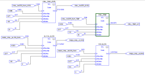
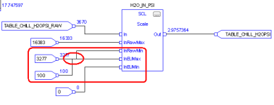
From the land of AB this is what analog inputs look like. Recent Chill water program I did.

4mA = 0% of a spanned instrument = raw value of 3277
20mA = 100% of spanned instrument= raw value of 16383

The CHILL_TANK_LEVEL raw value was changed for a quick adjustment, I need to go back and respan press transducer to correct.

If MicroLogix then Scale with Parameters instruction.

5000SCL.PNG
 
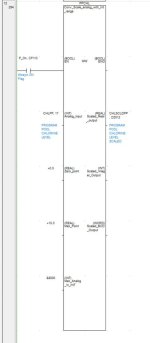
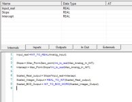
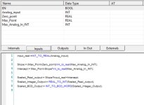
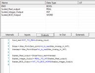
From the world of Omron. Pics show the outside of the block, inside of the block (ST) and several shots of this showing inputs, outputs and internals. Output by REAL, integer and BCD - integer and BCD lose the decimal points. Works really well - I normally use REAL but sometimes integer if I do not want tyhe resolution.

Scaling 1.jpg caling 2.JPG Scaling 3.JPG Scaling 4.JPG
 
Hi dcam, is that a typo/wire error or is there a reason you have 2 different inputs on H20_IN_PSI, InRawMin/InEuMax?
I imagine it is just very small gap that is not being displayed between the wires, but it may be confusing for some (me at least initially).
Kevin
 
Last edited:
Unsure what you mean.

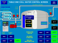
Not sure what you mean? There is only one input the H2O psi...just like the Glycol psi. Maybe im not seeing what you are pointing out. This is a pict of working logic. heres a pict of my PV. Please let me know in more detail what you are asking.

TableChill.PNG
 
just a guess - but I've got a hunch that he's talking about this area where the two lines overlap ... that's just something that happens with the FBD display from time to time ... dragging the signal references around a little bit usually clears it up ...

note that the code won't be confused by the "overlapped" display ...
.

overlap.PNG
 
Last edited:

Similar Topics

I know nothing about simaticnet OPC server. I do know Kepware. I would only ever scale raw to engineering in the PLC, but it is possible to scale...
Replies
5
Views
211
Hi all. I'm working on a rehab and I'm trying to figure stuff out. See screenshot at the bottom. Local:5:I.Data[6] in BTD instruction is a...
Replies
6
Views
700
Hello all, First post here. Hitting a wall with finding info on this topic online, and none of my coworkers have a clue. I have a PanelView...
Replies
10
Views
1,335
Hello, We monitor the temperature of a pipe via a 4-20mA temperature transducer. This goes into DB135(Read Analog Inputs). The issue I have is the...
Replies
0
Views
624
5069 IF8 with a 4-20ma 0-100psi, sealed fixed, no calibration, transducer attached. IF8 is scaled 4ma= 0 psi, 20ma=100psi. If over time the...
Replies
12
Views
2,580
Back
Top Bottom