MSG Command

Leeroy

Member
Join Date
Oct 2012
Location
Canada
Posts
66
Quick question on the message command in a SLC 5/03. Is it possible to read/write to multiple addresses that aren't adjacent to one another?

For example lets say I want to write a few values to another PLC, let's say the addresses are F8:0, N7:0 and N7:10. Is this possible with one message command or would I need to do 3 separate commands to do this?

I think the answer to this is no but just checking.
 
From reading the SLC 5/03 MSG Help file, each message can have only one address, but you can send up to 4 messages at any one time to different addresses, because there are 4 message channels.

SLC 5-03 MSG Instruction.jpg
 
Last edited:
What you're describing would be a 'data table scattered read". It's something that exists, just not in the SLC-500 family controllers.

In general, you can address a block of up to 124 words in a data table file with a single MSG instruction.

So to read F8:0, N7:0, and N7:10, you would need one MSG instruction to read the F8:x file, Length 1, and another MSG instruction to read the N7 file, length 11.
 
Just from a debugging standpoint I prefer to keep the reads and writes to contiguous data blocks in a separate message instruction for each. For most applications the difference in response time is insignificant compared to the time required for troubleshooting.
 
MSG Instruction Size in Elements - Part 1

I just wanted to make my contribution to this topic as I've seen it asked in various forms before and felt it needed some expansion/clarification...

Leeroy said:
Quick question on the message command in a SLC 5/03. Is it possible to read/write to multiple addresses that aren't adjacent to one another?

Quick answer - no.

Because you can only set a start address and a length in a MSG instruction, it will only read/write consecutive addresses from the start address, and only addresses from within the same Data File.

Leeroy said:
For example lets say I want to write a few values to another PLC, let's say the addresses are F8:0, N7:0 and N7:10. Is this possible with one message command or would I need to do 3 separate commands to do this?

Again, as F8 is in a different Data File to N7:0 and N:10, you would have to use one write MSG for F8.

You refer to N7:0 and N7:10. They are in the same Data File, but not consecutive. I would say two separate MSG instructions would be required here, as I don't know what N7:1 to N7:9 are doing in the destination PLC, or the source for that matter.

So, "3 seperate commands" would be required to write these 3 addresses from one PLC to another.

Ken Roach said:
So to read F8:0, N7:0, and N7:10, you would need one MSG instruction to read the F8:x file, Length 1, and another MSG instruction to read the N7 file, length 11.

Ken,

I know you were just giving a quick example of how to read the N7 Data File in one MSG. While that's clever to achieve it by using a length of 11, I'd just like to point out something that may require further consideration if doing so.

Leeroy's example question was to write N7:0 and N7:10, not read N7:0 to N7:10. Regardless of whether you are using a read or write MSG, the following would need consideration if setting a length of 11 elements in the MSG instruction. A length of 11 will read or write 11 consecutive elements(words) from the starting address N7:0. So obviously that's N7:0 to N7:10.

If we look at a write MSG required to go to N7:0 and N7:10 - depending on what the addresses are doing in the destination PLC, you may not want to write to N7:1 to N7:9. If those addresses were doing something different to the source PLC, you may overwrite important data while setting a length of 11.

Likewise with a read MSG - if you didn't want to overwrite N7:1 to N7:9 in the PLC you are reading into, you could not use a length of 11. You would have to use two separate MSG instructions for N7:0 and N7:10 to avoid this.

Consider even further...if the source and destination PLCs are sharing consecutive addresses N7:0 to N7:10 - depending on the structure of your logic, it may, or may not be required to read or write to all of that range of addresses at the same time.

Example:

If logic condition A - write N7:0 and N7:1 only (1xMSG,L=2)

If logic condition B - write N7:0 and N7:10 only (2xMSG,L=1)

If logic condition C - write N7:0 and N7:2 and N7:4 only (3xMSG,L=1)

If logic condition D - write N7:0 to N7:10 inclusive (1xMSG,L=11)

Any manner of logic could be possible.

If logic condition B applies - you have to use two seperate MSG instructions with a length of 1 each.

If logic condition D applies - you may use one MSG instruction with a length of 11.

Again, this is just to clarify that using a certain length in a MSG instruction, to reach non-consecutive addresses within the same Data File, may not always be ok.

Ken Roach said:
What you're describing would be a 'data table scattered read". It's something that exists, just not in the SLC-500 family controllers.

Ken, in a funny sort of way, if the inclusive addresses do not matter while using your short-cut method, you actually demonstrated a scattered read within the same Data File. :geek:

more to come...
 
MSG Instruction Size in Elements - Part 2

Ken Roach said:
In general, you can address a block of up to 124 words in a data table file with a single MSG instruction.

I appreciate that it's a general figure, but where is that 124 derived from? :confused:

I'd like to expand further on the limitations of the maximum number of consecutive elements allowed to be used in one MSG instruction, specifically while using the SLC5/03, but not exclusive to it.

This limit can be multi dependant...

Is it a 500CPU, 485CIF, PLC5 or Modbus message type?
Is it a read or write message?
Which data types are used?
Which controllers are being used?
Which protocol is being used?

A combination of some, or all of these permutations can decide what the limit will be.


Example MSG 1 - To demonstrate difference in message type:

Max T-Timer elements allowed for 500CPU = 34, for PLC5 = 20

a)
SLC5/03 < 500CPU read < SLC5/03
CH0 DF1 < CH0 DF1
T4:0 - T4:33 (34 elements)
MSG = Valid

b)
SLC5/03 < PLC5 read < PLC5/40
CH0 DF1 < CH0 DF1
T4:0 - T4:33 (34 elements)
MSG = Valid

c)
PLC5/40 < PLC5 read < SLC5/03
CH0 DF1 < CH0 DF1
T4:0 - T4:33 (34 elements)
MSG = Invalid


Example MSG 2 - To demonstrate difference in controller type:

Max N-Integer elements allowed for SLC5/03 = 103, for SLC5/02 = 41

a)
SLC5/03 < 500CPU read < SLC5/02
CH0 DF1 < CH0 DF1
N7:0 - N7:49 (50 elements)
MSG = Valid

b)
SLC5/02 < 500CPU read < SLC5/03
CH0 DF1 < CH0 DF1
N7:0 - N7:49 (50 elements)
MSG = Invalid


Example MSG 3 - To demonstrate difference between read/write:

Max C-Counter elements allowed for SLC5/03 read/write = 34, for a read from an SLC5/02 = 34(set by other controller limit), for a write to an SLC5/02 = 13

a)
SLC5/03 < 500CPU read < SLC5/02
CH0 DF1 < CH0 DF1
C4:0 - C4:33 (34 elements)
MSG = Valid

b)
SLC5/03 > 500CPU write > SLC5/02
CH0 DF1 > CH0 DF1
C4:0 - C4:33 (34 elements)
MSG = Invalid


Example MSG 4 - To demonstrate difference between protocols:

Max B-Binary elements allowed for DF1 on SLC5/03 = 103, for Modbus on SLC5/03 = 116

a)
SLC5/03 < Modbus 03 Read Holding Registers < MicroLogix 1400
CH0 Modbus RTU Master < CH0 Modbus RTU Slave
B3:0 - B3:115 (116 elements)
MSG = Valid

b)
SLC5/03 < 500CPU read < MicroLogix 1400
CH0 DF1 < CH0 DF1
B3:0 - B3:115 (116 elements)
MSG = Invalid


If you're getting into large MSG lengths, you really need to look up the "Size in Elements" limits for your specific hardware within the Local or Remote network you're going to be transmitting messages across.

More to come...
 
MSG Instruction Transmission Buffer and Queue

Lancie1,

Just to clear up what you found...

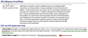
What you posted from the help files is the info on the number of message buffers available for each communication channel and how they operate depending on the number of MSG instructions being executed at any one time.

There are 2 communication channels, or ports, on the SLC5/03(CH0 & CH1). Each port has 4 "channel dependant" buffers available to queue the MSG instructions for that port. So that makes 8 buffers between the 2 comm ports.

For each MSG instruction you have to assign a Control Block to hold data for the MSG. This is 14 elements long, so usually a dedicated N Data File of 14 elements is created for each MSG instruction. You then enter the first element of that N Data File into your MSG parameter "Control Block" - eg. N9:0. This is not the "target file address" you underlined. The Control Block stores the "Size in Elements", in word 2 of its 14 words, that you have entered in the MSG "Setup Screen". The fixed "Control Block Length" of 14 that you pointed to is just a read only parameter. The fact it cannot be "altered" does not restrict how many elements can be entered in the MSG instruction, as I'm sure you're aware by now.

If 1 MSG is enabled, say a write MSG, it enters the first available buffer of four for that port, including the data to be sent. It awaits transmission at the next communication service interval, usually at the end of the scan. While the MSG is in the buffer waiting, it's Enabled(EN) and Enabled-Waiting(EW) bits are set in word 0 of the Control Block.

If 4 MSG instructions are enabled before the communication service interval, the buffer for that port is now full. If a fifth MSG instruction is now enabled while the buffer is still full, it goes into a FIFO overflow queue for that port. If subsequent MSG instructions are enabled at the same time before the communication service interval, a max of 10 MSG instructions can be queued(MSG 5-14) in the overflow FIFO. Only the header blocks of the MSG data are placed in this queue. While in the queue, only the EN bit is set.

Any further MSG instructions enabled, beyond the first 14, while the buffer and queue are full, will have their Waiting-for-Queue(WQ) bit set.

Once the communication service interval clears the 4 buffers for the port, the FIFO queue shifts the first 4 EN messages into the buffer which now also sets their EW bits and the first 4 WQ status messages will enter the queue in the order they are re-scanned. Their WQ bit is reset, and EN bit is set.

Note: For Modbus only 1 MSG can be buffered at a time and 10 queued (MSG 2-11).

There is no limit on the total ammount of messages that can be at WQ status at one time, but it's possible that some of these WQ messages may never get into the queue, depending on where they are in the scan.

That's why it's good practice to know how many messages can be enabled at one time between the buffer and queue and keep your program MSG excecutions inside this limit.

Either use an SVC instruction in the middle of the program, or after a block of 14 or less enabled messages.

I like to use the Timeout(TO) bit for each MSG. If left at the default 0, once the Start(ST) bit is set, the MSG waits indefinitely for a reply from the target. If you set a value of say 2 seconds, it will timeout the MSG and set the Error(ER) bit, which most of us use on a parallel branch to the Done(DN) bit to unlatch the Enable(EN) bit. The TO bit will reset the next time the rung goes from false-to-true.

Hopefully some of this will help someone struggling with MSG issues.

G.
 

Similar Topics

Hello everyone, I've got L30ER using MSG command to read data from two Micrologix. The command is working correctly, my data comes in OK. I then...
Replies
6
Views
1,788
Hello! Guys! I finally solved the problem of convert S5 to S7 ! Really thank you for your advice! And then, I have a question about command in...
Replies
3
Views
1,504
I have two PLCs both SLC5/4 that communicate with each other every once in a while. They share status information and part location information...
Replies
13
Views
3,038
Hello Everyone. I am using a 1769-SM2 Module to communicate Modbus RTU to a third party device, using the first serial port. I am using MSG...
Replies
0
Views
3,345
Unconventional I assume, but wondering if this works. If i built a listener in some other language and set the multi-hop ip to that of the PC...
Replies
8
Views
3,489
Back
Top Bottom