Lenze VFD F.OF1 error with no output connected

Jim Jones

Member
Join Date
Nov 2019
Location
Calgary
Posts
2
We picked up a Lenze SMVector 5HP drive and it worked for a short while but now it only shows F.0F1 error upon startup.

As part of troubleshooting, we disconnected the drive from motor and restarted the VFD...same error and it won't complete start up (cannot go beyond this step and access options)

That error translates to an Ground Fault issue but having no output device connected, it's something internal to the VFD. We assumed it might be a rectifier and I found a test procedure using multimeter w/diode function and using the mm leads in various position across the output terminals/ground and what the expected readings should be (either OPEN or approx .5V). VFD tests okay with that procedure


Had a chat with Lenze and they stated it's most likely a failed output transistor but the price to repair is nearly 2/3 price to replace the drive.

I know that this isnt a programming question but of course, a non-functional VFD is also not programmable...and we were intending on keeping the unit and customizing some of the programming to make better use of this unit e.g. add an e-brake option, change ramp up/down parameters, etc.

Anyone here familiar enough with SMvector VFD's that know where this component is on the board and how to test it?
 
Last edited:
We picked up a Lenze SMVector 5HP drive and it worked for a short while but now it only shows F.0F1 error upon startup.

As part of troubleshooting, we disconnected the drive from motor and restarted the VFD...same error and it won't complete start up (cannot go beyond this step and access options)

That error translates to an Ground Fault issue but having no output device connected, it's something internal to the VFD. We assumed it might be a rectifier and I found a test procedure using multimeter w/diode function and using the mm leads in various position across the output terminals/ground and what the expected readings should be (either OPEN or approx .5V). VFD tests okay with that procedure


Had a chat with Lenze and they stated it's most likely a failed output transistor but the price to repair is nearly 2/3 price to replace the drive.

I know that this isnt a programming question but of course, a non-functional VFD is also not programmable...and we were intending on keeping the unit and customizing some of the programming to make better use of this unit e.g. add an e-brake option, change ramp up/down parameters, etc.

Anyone here familiar enough with SMvector VFD's that know where this component is on the board and how to test it?
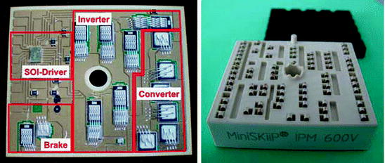
On small drives like that (and some larger ones), the transistors, diode bridge and firing circuits are all integrated into a single unit called an "IPM" (Intelligent Power Module), about the size of a credit card, only thicker. The components inside are not individually replaceable, it's all surface mount technology now. Yes, you can replace the entire IPM if you are REALLY handy with a soldering iron, but the module is what is costing 2/3 of the VFD replacement cost.

This is what it looks like:
0818-pfc-inverter-ipm-intelligent-power-module-in-21mm-36mm-for-low-power-drives.jpg

Here is a larger one that has been opened up and the potting goop removed:
978-3-642-11125-9_14_Fig11_HTML.jpg
 
F.0F1 error

Indeed there is an IC-looking device soldered to the board/backed on to the heatsink. There are 2 rectifiers also adjacent/backed on to the heatsink. Originally was hoping it was one of the recitfiers blown since that is 1) easy to test 2) cheap to replace....but tests confirmed they are still intact. There are also a number of SMD's soldered around but judging from the size (small), figured they worked on the logic side of the VFD and not the actual current path.

Read somewhere else the an IBGT could be the culprip since it is a 1) high power 2) transistor-based device...but I see nothing on the board that would resemble a IBGT since it too would also have to be mounted to the heatsink.

If it really is something toasted within the IC, then agreed that this would be a toss-away device.
 

Similar Topics

Dear All, I have a stitching machine which use Lenze VFD that suddenly stop and could not run again. There is a message on operator screen...
Replies
5
Views
2,168
Hi there, I have a project that need to use IDEC FC6A modbus to control a VFD which is Lenze SMVector. I'm new to PLC and never done...
Replies
2
Views
2,488
Has anyone here used the new VFDs from Lenze? The i510 series. I'm planning to buy a micro drive but would like any comments if you have used it...
Replies
3
Views
2,772
hi all, i am building a new conveyor system and i have to use lenze smd vfds. i am not much familiar to them, and i have no time for reading big...
Replies
7
Views
3,156
Hi folk, I would like to know what kind of Parameters should I setup for controlling with Profibus. My old Lenze 8200 motec 0.25kW have a busted...
Replies
0
Views
56
Back
Top Bottom