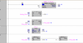
Flow totalizer

jpmorasse

Member
Join Date
Feb 2021
Location
Alma
Posts
2
Hi all,

I am kind of new to PLC programming and I am currently trying to learn all this fun stuff by myself.

I got myself a productivity 2000 from AD with some card to make some test and to understand plc programming.

I have read all the other thread talking about this subjet on this forum but I am not able to solve my problem actually.

I whant to make a totalizer from an analog flow meter (IMF SV8050)

1. I scale my input
2. Make a Timer to sample the rate periodically
total = (flow*samplerate)+total

So If I use the simulator in Productivity using those spec to make test

Flow= 60lpm (1lps)
Samplerate = 1s

I should get 60 as total after 60s.

The problem I have is when i run the program I get 44 count after 60s and I am not able to understand why

Thank a lot if you can help me I will be very happy.

PS. Sorry for my english It's not my first language.

2021-02-07_00h00_01.png
 
First of all, using the timer value instead of the done bit will not make any difference due to scan as if the timer times out at 1.5 seconds you still have the same problem, and you are missing 0.5 seconds try first to just use the timer done bit to do the maths and update the total, looking at it 40 against expected 60 is the 0.5 second so set the timer to 100 (1 sec)
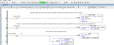
I do not have AD so here is a similar program ignore the counter & for this example I reset the flow totalizer just to prove it will log 60 every minute so just use the timer up bit to do the maths.
Timer.done
----|/|----------------[Timer 100] // one second timer
Timer.Done
-----| |--------------[MATHs...........] // use the timer done bit to do the maths

You do not need to reset the timer value

Totaliser.png
 
For a totalization calculation (Integration) having a precise time base is essential

In both examples that you have shown, the time calculation is not very precise since it will count the timer preset time + 1 scan time.

The timer should be reset immediately on the same scan or use another way based for example on the system clock
 
I agree, it will depend on the scan time so either use a timed interrupt or reset the timer (this will still have small errors depending on scan time).
On my example according to the data for that PLC a 100ms time base at 1 second intervals the timer is accurate to 10 pulses per million + 1.5 scan time
however, using the high speed timer in an interrupt if used over a period of 24 hours the error is 0.8 seconds. This is according to the manual and the timer contact is used after the timer and not before.
 
Welcome to the forum!


I agree with the previous responses, but here are my two cents:

Analyzing the OP program


What the OP program tries to do is sample data at 1s intervals and totalize the flow at each 1s (=100cs) interval:

  • (FLOW_LPM/60) is Volume/s
    • (Volume/min) / (s/min) => Volume/s
  • "*1" is integrating an assumed constant volume flow rate over 1s to calculate a Volume
    • (Volume/s) * 1s => Volume
  • "+ FLOW_TOT" totalizes the flow
  • Presumably the OP program is also showing the total after 60s, perhaps with another timer that is not shown
So the math is correct, but the program has an assumption that the sampling occurs at 1s intervals, and that assumption is questionable at best.

What the OP program actually does, is the same math, but at an effective average interval of around 1.36s (136cs; i.e. 60/44). This is essentially what the other responses are saying, and their solution is to make the actual interval closer to the 1s implied by the "*1" term of the formula.

Sidebar
N.B. 1.36s (136cs i.e. 36% error average, so maybe 72% max per step, 720ms max on one scan?) seems a bit long; I would expect the timing accuracy to be closer to 1-2% i.e. average lost time is 10-20ms per totalizing step; certainly no more than 5% (100ms time lost max on any one scan, so ~50ms expected average). So an alternative explanation is that calculations are all being done with integers and there is truncation going on e.g. FLOW_LPM is 59 and 59/60 is 0 for ~25% of the totalizing steps.

One way to verify that the average totalizing step is 136cs is to count the number of totalizing steps per minute. If it around 44, then timing is the problem; if it is 49-50 or more, then there is an additional source of inaccuracy.
Fix the timing

As suggested in the previous responses, if the program keeps the existing formula, with its assumption of 1s (100cs) sampling intervals, then the solution must be to make reality conform to the assumption. @parky suggested using an interrupt routine, which should work. Another approach would be to change the timer counter target ensure 60 samples occur per minute. At present it seems to be 44 samples per minute with a target of 100; that suggests changing the scan interval target from its current value of 100 to around 70-75 would be expected to yield the desired 1s sample rate and 60 samples per minute. That calibration could be made and might be an interesting experiment, but in practice it would need to be checked regularly, especially if the program ever changed.

Fix the timing calculation

Another way to fix the timing issue would be to drop the assumption that the sample interval is 100cs. To do this, modify the formula to weight each sample by its actual interval duration (integration duration), i.e. use

  • "* (PULSE_CURRENT/100.0)" i.e. (cs / (cs/s)) => s
  • instead of
  • "*1"
That could still have some error, but is should be less, if timing is indeed the entire issue.

Ignore timing interval


Another approach would be to recognize that the totalization formula is currently a weighted average, and instead of trying to weight the sample by the duration of the sample, simply sum the samples but also count the number of samples at each sample time:
FLOW_TOT <= FLOW_LPM + FLOW_TOT
SAMPLE_COUNT <= 1 + SAMPLE_COUNT​
then, at the end of one minute, perform the average:
FLOW_TOT <= FLOW_TOT / SAMPLE_COUNT
This takes a different approach from that intended by the original program. But in a Gaussian-noise world and 40-60 samples per minute, I doubt it has any less validity than the timing interval corrections above. Because even if we can accurately correct (or measure) the actual sample interval, we are still using a single FLOW_LPM sample on one scan, along with its (Gaussian?) noise, on that one scan to represent the average flow over that entire sample interval. So whether we take 60 weighted samples (correct the sampling interval to 100cs), or 44 weighted samples (measure the sampling intervals), or 44 non-weighted samples over the minute (average however many samples we get), the expected errors and accuracy will be about the same.


P.S. there is no need to apologize for your english language skills; I am sure they are infinitely better than my skills in your first language.
 
Last edited:
In the last rung, when the timer's accumulated value is greater then 100, by zeroing the accumulated value you are losing the excess. Instead of using the COPY instruction to clear the timer's accumulated value, subtract 100 from PULSE_CURRENT.
 
In the last rung, when the timer's accumulated value is greater then 100, by zeroing the accumulated value you are losing the excess. Instead of using the COPY instruction to clear the timer's accumulated value, subtract 100 from PULSE_CURRENT.


Ooh, I like it, but it still likely loses the last (60th) sample, so the result may be systematically low by ~2%.


Question for the OP: how does the program determine that sixty 1s samples have been taken?


I am still suspicious that the ~27% error has a cause other than one-second timing inaccuracy.
 
I suspect the timer will not reset until it reaches 150 (1.5 Secs), I doubt the timer will reset on putting a zero into the accumulated word (pulse_Current) It seems to be an IEC timer & I have tried on a couple of IDE's & it will not reset the timer until the 1.5 secs is up, however, not used this platform so cannot be sure.
 
There is no need to reset the timer. The logic is simply testing its accumulated value to detect one second or more elapsed time. When it detects the passage of another second it increments the flow accumulator and (if the OP follows my suggestion) subtracts one second from the timer accumulator. So if the timer accumulator happened to be at 105 when the comparison on rung 3 was true, subtracting 100 from PULSE_CURRENT would leave a remainder of 5.
 
P.S. there is no need to apologize for your english language skills; I am sure they are infinitely better than my skills in your first language.


I just wanted to say that your write-up was on point, and I appreciate the time it took for you to do that.


For OP, I would just like to give a little non-technical insight into their totalization problem:


Anytime you are collectively accumulating anything in a digital system, you must be aware that there is drift and error. You then need to establish at what point that drift will take you out of tolerance.


This is why totalizers are often dedicated hardware that ONLY totalize.
 
It's hard to imagine my suggestion fixing everything. Sixty samples represents 6000 "ticks" in a 10 millisecond timer. The OP reported only an accumulated count of 44 liters based on a 1 liter per second flow. Resetting the timer each time its accumulated value equaled or exceeded 1 second (100 ticks), would have to have lost 1600 ticks or an average of more than 36 ticks per reset which seems unlikely.
The most likely culprit is round-off error in scaling the analog flow signal, especially if the the Scale_Linear function uses integers as appears likely.
 
We cannot see the status of the scale block, the min/max seem unusual never had an analogue use such high values but then they could be 32 bit conversion, also as op is using simulator it looks like he is putting a fixed raw value into the scale block has the op got the value correct for 60 LPM The max value
is 2,147,483,647 Really ????
That works out at 14,316,548.933 per litre so the value in the raw analogue would be 858,992,936 or do my eyes deceive me.
 
It's hard to imagine my suggestion fixing everything. Sixty samples represents 6000 "ticks" in a 10 millisecond timer. The OP reported only an accumulated count of 44 liters based on a 1 liter per second flow. Resetting the timer each time its accumulated value equaled or exceeded 1 second (100 ticks), would have to have lost 1600 ticks or an average of more than 36 ticks per reset which seems unlikely.
The most likely culprit is round-off error in scaling the analog flow signal, especially if the the Scale_Linear function uses integers as appears likely.


That is a good point. Here is the manual page. The input and output can be any of the numerical types, including floating-point. These also appear to be 16-bit modules.


https://www.automationdirect.com/microsites/productivity/software/help/Content/119.htm
 
Last edited:
13,107 is correct for 4ma but the max input should be 65,535 according to the document, so where he got that value from I have no idea.
 
Buy a meter with pulse output

I've got much agreement with what has been posted. My answer is to use a pulse output meter and count the pulses. I try to avoid integrating 4-20 milliamp stuff whenever I can.
 

Similar Topics

Hi; We installed an orifice plate type steam flow transmitter which configured to give 4-20mA signal correspond to 0-9ton. I given that signal...
Replies
24
Views
5,605
Hello. I wanted to write the logic of the flow totalizer and the flow itself for self-education in RSLogix5000 V20.01 software. After reading the...
Replies
13
Views
7,541
Hello I was needing some guidance on communicating and setting up a totalizer from a flow meter in the PLC. The PLC is a AB 1769 Compact Logic...
Replies
1
Views
1,783
hi, so i m very new to plc programming.Below is my requirement I have to create a program folder for totalizer with individual FBD routine for...
Replies
17
Views
4,255
Dear Experts,:) I have E&H flow meter (promag L400 ,5L4C4F, DN450) which has pulse o/p with these specs: Pulse width Adjustable:0.05 to 2000 ms...
Replies
4
Views
2,106
Back
Top Bottom