PID Trainer, issue on setup

  • On top of that, an RC analog servo typically works with a duty cycle (ON duration) of between 1% and 2%, or maybe up to 2.5%, of the PWM period.
  • The 1400 PWMX.DC (Duty Cycle; cf. here) setting has a range of 0 (0% Duty Cycle i.e. always off) to 1000 (100% Duty Cycle i.e. always on).
  • So that 1-2% range will mean the CV output to the PWM.DC control parameter will have a usable range of 10-20 out of 1000, or only 11 discrete values.
I have been trying to come up with a solution to this. Does the following seem feasible?

If we configure the MicroLogix (ML) PWM for 800Hz, there are 800k PWM "k-counts" per second, or 800 k-counts per ms, and the period is 1.25ms.

If the servo PWM frequency is 20Hz, then its period is 50ms, and (full servo range) of 1-2% of that is 0.5-1.0ms, or 400-800 k-counts, and there will be 40 MicroLogix PWM cycles per servo.

If the servo PWM frequency is 50Hz, then its period is 20ms, and 1-2% of that is 0.2-0.4ms, or 160-320 kcounts, and there will be 16 MicroLogix PWM cycles per servo.

The trick would be turning "off" 39 out of 40 (20Hz servo) or 15 out of 16 (50Hz servo) of the ML PWM cycles.

It could be done in hardware (external breadboard) with a counter triggered on the falling edge of the MicroLogix PWM signal.

Or perhaps it could be done in software with a 1ms STI program task that enables the MicroLogix PWM for only one STI cycle out of 50 or out of 20. The questions are whether the ML PWM starts as soon as its enable bit becomes 1, and whether writing a 1 to that bit in software is only an indication of what the ML PWM should do the next time it is scheduled to run and if so how long that schedule is delayed before executing. The nice part about this approach is that this STI task is also a good place to execute a loop update for the PID, which update will then be in synch with the servo PWM signal.

If one of these approaches could be made to work, it might solve the resolution problem, at least to the point where resolution disappears as an issue compared to backlash in the linkage.
 
While you fry your eggs over the fire, minor corrections for page 2:etc. But that changes neither the approach nor the general result.
where does the sin2 come from all of a sudden?
The 5.88 we agreed upon is correct.
It is derived from equating and solving mgh=(1/2)*m*v^2+(1/2)I*ω^2 and making a few substitutions.
 
where does the sin2 come from all of a sudden?
Its necessity was originally noted by @MaxK over half a century ago, and explained in some detail since, so it's not all of a sudden. Your lack of understanding is likely due to your self-admitted laziness (which I admire).
The 5.88 we agreed upon is correct.
@MaxK and I have agreed on 4.2 for most of the past week. I assumed it doesn't matter, qualitatively, for what you are doing, so you'd catch up eventually, which eventually is today, I guess.

Do I need to provide links, or can your mouse hand manage to struggle through some scrolling?

11b3bbbf-3d83-435b-b564-a2715b1434f0.c5b9bd925f7e88676d03179919c33b79.jpeg
 
Last edited:
I was going to have a fan oscillate to give another dimension but I cant get this one let alone introducing more variables

I will try to give simple guidelines for tuning a PD controller in a closed loop (when the PD controller is running).
Let me clarify that the described method does not give an “exact solution”, but gradually brings the system closer to the required parameters.

Experiment

Before start experiment ball should be placed to the setpoint (i.e. Error = 0).
Run PD control.
Apply impulse disturbance - hit the ball shortly.

Data analysis

Form of the PD algorithm

CV = Kc* (Error + Td * DeltaError / Delta t)

Td calculation

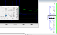
Take a look at the attached chart.
At the point CV_0 (immediately after hitting the ball) P-term = 0 i.e. CV value = D-term value
At the point CV_1 (When the deviation of the position of the ball reaches its maximum) D-term = 0 i.e. CV value = P-term value.

(P and D curves (Up, Ud) are not needed to apply the method, they are provided to illustrate why the values are taken exactly at the points CV_0 and CV_1)

CV value at point CV_0 = -12.5
CV value at point CV_1 = - 3.7

Let's find the ratio of CV values at the points CV_0 and CV_1 (this ratio shows how big or small the D-term is)

-12.5 /- 3.7 = 3.38

I propose to consider 2.8 as the target value (but this is not a dogma)

To calculate the new Td, I propose the following "formula"

Td = Td(current) * (2.8 * - 3.7 / -12.5) ^ 0.75

Kc calculation

An increasing Kc leads to a higher CV rate. The limitation on the increase in Kc is the speed limit of the actuator.
Pay your attention to the points CV_max and AC_max. As you can see the actuator reaches its maximum position with a temporary Delay. Actuator Delay Factor :

(t CV_max - t AC_max) / (t AC_min - t AC_max) = (2.97 - 3.72) / (1.45 - 3.72) = 0.33

It is difficult to specify some "ideal" value of the Actuator Delay Factor due to the uncertainty of the characteristics of real systems. I would suggest bringing the system to Actuator Delay Factor = 0.25 using the following approximate formula

Kc = Kc(current) * desired value * (t AC_min - t AC_max) / (t CV_max - t AC_max) = Kc(current) * 0.25 * (1.45 - 3.72) / (2.97 - 3.72)

The decision to increase / decrease Kc, I would take in accordance with the results of the experiment with the new parameters.

Tuning.jpg
 
@geniusintraining:

Enough theory, as @MaxK suggests, it is time we characterize the actual system.

A) What is the sample rate of the raw position measurement?

B) I think the first video said the range is something like 300 to 29000; is that correct?

Could you make a table of ΔCV vs. time to travel the entire length of the beam? Like this:

  1. Set ΔCV to 1
  2. Start with CV = CVBase,
    1. where CVBase is a value just below a point where the ball is balanced,
    2. Hold the CV at CVBase until the ball is resting on the stop at one end of the beam.
  3. Increase CV by ΔCV as a step change as quickly as possible,
  4. If the ball does not move off the stop, then increase ΔCV by 1 and return to Step 2
    1. This may happen several times because of friction
  5. If the ball does move off the stop, wait until the ball rolls the full length of the beam, then record the time it takes to get to the other stop at the current value of ΔCV i.e. [ΔCV,Time]
    1. Even better, save three values in the columns of a spreadsheet:
      1. ΔCV
      2. Time to move from stop to stop
      3. A = 2 * D / Time2
        1. where D is the raw PV to the PID i.e. measured ball movement along the beam, from stop to stop
  6. Increase ΔCV by 1 and return to Step 2.
    1. As an improvement, make several runs at each value of ΔCV to improve the statistics
At the end, fit a regression line to ΔCV vs. A i.e. A = m ΔCV + b (even Google Sheets can do this, I think):

  • The slope, m, will be our K
    • I.e. 5.88 scaled by sin-2Γ and by all of the sensor and servo configuration
    • The units will be PVunits s-2 CVunits-1
      • SI and US/English units are irrelevant
  • b will be K * (CVLevel - CVBase), so the PID Feedback bias should be set to
    • CVLevel = CVBase + b / K
This could be automated in the PLC cf. here.

This could also be done in the other direction i.e. start at a positive ΔCV, i.e. CV = CVBase + ΔCV, that always rolls the ball to the other end, and then start decreasing ΔCV, and the D values are negative.

Caveat

This model approximates acceleration (and sin(θBeam) as linear with CV, which has its advantages and disadvantages. the main advantages are that it is should be a good approximation near CVLevel, and for that reason it may be worth limiting the range of ΔCV to test.
 
Last edited:
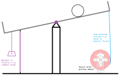
Here is a design that will have the servo angle characteristic very nearly linear with sin(θBeam) and therefore with acceleration.

Untitled.png
 
Ouch-shi...! I'm goddamn perfunctory narcissistic dumb***!!!

Pay attention to #18 curves. PV curve peaks superimposed on CV curve troughs
i.e. the PV and SV curves are in antiphase,
i.e. The D-term is extremely small.

If I'm right, then 3 conclusions can be drawn from this:
1. On the #18 graphs, the system is stabilized rather than by the PID controller, but by friction. I.e. the PID trainer is controllable (Honestly, I have no idea how, with such control, it was possible to stabilize system... @geniusintraining smeared the ball with glue? ))) ).
2. Apparently Micro800/CCW PID-instruction should be understood as follows:
CV = blahblah + Kc / 100% * ( 1 + blahblah + Td / 100% * blahblah)

3. 9 pages of self-admiration were absolutely in vain. Back in post 19, we could give a simple and understandable advice:

Increase Td by several times (the current value is extremely low), it may be necessary to reduce Kc somewhat - a decision on this will need to be made based on the results of experiments with increased Td.
 
Last edited:
The must be damping. Either mechanical or electrical.

2. Apparently Micro800/CCW PID-instruction should be understood as follows:
CV = blahblah + Kc / 100% * ( 1 + blahblah + Td / 100% * blahblah)
The ML1400 gains are unitless. The time constants are in minutes and the calculations are done using integers. Yuk. I have never liked the way Rockwell implments the gain part.

3. 9 pages of self-admiration were absolutely in vain. Back in post 19, we could give a simple and understandable advice:
Yes, it is hard. I said so up front. Calculating the gains given the model is easy. The problem is getting the model and we don't have that. Only our theoretical one.

Increase Td by several times (the current value is extremely low),
Yes but the response isn't damped well.

it may be necessary to reduce Kc somewhat - a decision on this will need to be made based on the results of experiments with increased Td.
The value of Kc is not as important as getting noise free feedback for the Td to act on.

GIT's example has the ball going back and forth many times before it settles out.

I would modify drbitboy's diagram. I would have a big pulley on the rotating point and a small pulley on the motor to gear down the motor and effectively increase the resolution. The tilt angle doesn't need to be that much.
 
...
I would modify drbitboy's diagram. I would have a big pulley on the rotating point and a small pulley on the motor to gear down the motor and effectively increase the resolution. The tilt angle doesn't need to be that much.

With gears and a large mechanical advantage I would be concerned about backlash, but the primary points of that diagram are near-linearity and feasibility: I have more dental floss lying around the house than gears, and I can make that pulley wheel with a hole saw, a drill, and a round file. The mechanical advantage is set by the locations of the fulcrum and the servo, and the radius of the wheel.

The need for linearity is marginal, admittedly
 
I hope to get back to this later next week

@Geniusintraining I kindly ask you to tune the PID controller as described in post 124
I will hardly ever have the opportunity to test the method on real process (k / s ^ 2). I really want to understand how efficient the described method is.
 
Hi Max,

I will be getting back on this soon, because I am the owner of the business this is the absolute worse time of the year.... TAX SEASON, I have a few days left of paperwork then back to making things :)

I still have a couple other projects that I need to work on also

I tried to hire drbitboy but that project fell through, maybe I should hire him on this one and send the trainer to him but lets see if I get some free time
 
So I tried what Max said and it got me this close (below), sorry Max but did not understand everything and I did end up having to use all 3 P, I and D.. that did show me that the issue is mechanical and cant be solved by a PID tune I need to fix it first.

Also found that is I sent my trainer less than 4ma or more than 20ma it would act really funny and not funny ha ha, I ended up making a min/max that the PLC can send the trainer, so one issue solved.

See below, Red is SP, Green is CV and Blue is PV. The ball was only 4 away from SP, with this tune the CV is making small movements trying to get the ball to SP but the CV had to move WAY to much for the ball to even start moving, I tried buffing out the rail and have other balls on the way, these balls are nice and round (not like DR's) as time allows I will continue to solve the mechanics then get back to the PID once thats done.

Thanks for the help so far...

PID3.png
 

Similar Topics

I have Real PLC but I dont have a real system to have PID Control- any recommendation how can I build such a system- there are some PID trainer...
Replies
6
Views
3,091
I've built a little trainer with a Automation Direct DL05, some pilot lights, switches, a ethernet card and some of the new PX remote I\O. The PX...
Replies
7
Views
4,228
Hi, I would like to assemble a simulator/practice booster pump system that uses PID to maintain steady water pressure under various outlet demands...
Replies
0
Views
72
Hello, I have a motor that we are sending a RPM Speed Output from 0-100% to the VFD. However, the Motor HP needs to be limited to 6000 HP and the...
Replies
3
Views
88
I have S7 1512C controler for controlling 48 PID temperature loop, the output is PWM. Please I need the best, most efficient way to write the...
Replies
13
Views
601
Back
Top Bottom