CU240E-2 DI0 does not work

Piiok

Member
Join Date
Dec 2022
Location
Poland
Posts
4
HI,

I'm using siemens G120 drive with CU240E-2. Previously was working DI0, DI2 and DI 4 in configuration with COM 1.
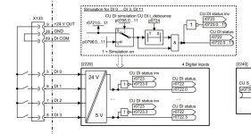
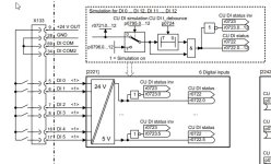
Unfortunately right now DI0 doesn't work, when I'm connected via TIA Portal 16, Sinamics Startdrive advanced. DI 2 and DI 4 still working.
This drive works on the production line and I don't know if sb change in params.

Does exist some parameters regarding digital inputs to activate/deactivate it ?
 
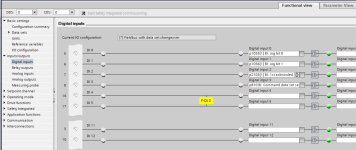
What does the input look like in Startdrive?
Is the "led" for DI0 on?
Are you getting 24vdc to the input? put your voltmeter between terminals 5 and 28
How is the input programmed?

cu240e di0.jpg
 
Hi thank you for your reply JRW.

What does the input look like in Startdrive?
answer:
my original conf was like in attached photo. Right now I changed p840[0] from DI0 to DI4 because DI0 does not change its status to high even if I put 24 voltage.


Is the "led" for DI0 on?
answer:
No. I put 24 V on it, and no high status. But DI2 and DI4 work correctly, 24V to input and in software I get high status for them.

Are you getting 24vdc to the input?
answer:
Yes I measured it. But I don't use 28 GND. I'm using COM 1 for low potential 0V.
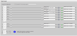
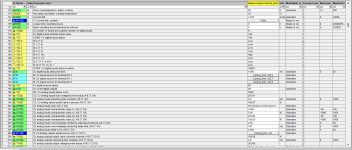
How is the input programmed?
answer:
you can see in attached files.

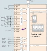
My another question is, how to wired correctly to use another inputs DI1,DI3,DI5 ?

configuration.png Starter_1.png
 
Hi JRW,

Thank you for your reply. Sorry for late answer but I've already today had access to machine.
DI0 looks is doesn't work at all.

Anyway, I went by your advice and configured another input DI1 (instead DI0) using COM 2. COM 1 and COM 2 have right now the same 0 potential.

I'll observe how does it work and if there is no other malfunctions.

If could you have some tips how to protect digital inputs against overvoltage I would be greatfull. And also what kind of supplier to use.

Right now I have separated galvanically, supply of digital inputs with digital outputs of beckhoff card by relays.

Thank you for all very helpfull information !
 
Hello again,

I would like to refresh subject.

Recently once again one input DI4 with signal p840 ON/OFF was damaged (I cannot see any change of status in software although it is energized 24V).

This happend second time, for a first time damaged was DI0, right now DI4.

Inputs are energized from DELTA 24V supplier. Electric voltage is ,controlled via relays which are sterring by PLC.

What could be the reason that two inputs were damaged ?
 
I think that maybe you get voltage spikes on the common 0V. And possibly it is just a coincidence that it is the VFD inputs that gets damaged before anything else.

Check if you have large contactors, solenoids or any other inductive loads, that they are equipped with surge suppressors. If the inductive loads are on a different voltage system but share the same ground, it can affect also the 24V system.
Check that your 0V is grounded.
Check that your earth is good enough.
 

Similar Topics

hi am a beginner in controlling the G120 VFD can you give an easy-to-understand source about controlling G120 vfd with (CU240e-2-pn) unit using...
Replies
2
Views
753
Is it possible to update the firmware of the device in the title through TIA Portal?
Replies
3
Views
2,061
Hello, I need to program a CU240E v4.4 with a PM240 power module and a BOP-2. The client wants following DI mapping. DI 0: Start remote...
Replies
0
Views
1,574
I am trying to connect with a Schneider plc which has a firmware version only available in Somachine v4.2. In Machine expert After taking upload...
Replies
0
Views
112
Back
Top Bottom