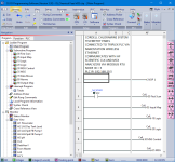
Is it possible to program this onto a Click PLC? If so, I need help anyway.

Just found out that the HMI you have will not diplay or input float numbers only integers, you cannot use integer DS type registers on the analogs, I have been looking at the HMI software numeric input & display & I certainly cannot find any way of changing it, still you get what you pay for šŸ™ƒ
The only way would be to multiply the float by 10 (1 decimal place) then convert it to an integer. or if you do not need decimal places then just convert from float to integer.
Just looked it appears there is no instruction but it does seem you can use the copy function to copy a float to integer.
EDIT: Just closed it down & opened it up again & it now allows me to add a float, it's definitely buggy
 
Last edited:
Right just to give you a head start attached is V3 of the program with just a slow setpoint plus a really rough & ready HMI, I have only just stuck some fields on to show you examples of input fields, read only fields, multiple text message i.e. use for the sequence status, how to enable & flash messages based on bits & use the same bits to hide them.
EDIT: There are a number of ways to display text or turn it off, you could put those on top of each other in runtime as only one message will be enabled at a time
The screen is small so you could have a screen for the operation & one for the editing of the test parameters I will be on my way to Thailand for some warm weather but will log on when I can
 
Last edited:
I got "done" with the code. I added some more things here and there that I think would work. Like more safety features and just useful things. Let me know if it looks fine I will ask questions tommorow or later today. I am about to leave work. Thank you guys for the help, I feel like I understand now how to code PLCs on a basic level. The only difficult part for me is scrolling through each sequence and seeing if the outputs and instructions interfere with anything else. I looked at this for a couple hours and finally said yes it should work. Probably very buggy but let me know if there are any problems.

https://online.flippingbook.com/view/499548453/

Also, if you didn't see I posted a diagram and explained how our pump worked on page 5. The pumps air is compressed to like 140psi, so it's just pulling in 140psi of air until it reaches the pressure it wants.
 
Last edited:
Nice work so far, although I haven't studied it closely, I did see that you added comments. I did not find a page 5 though.

Can you zip and attach the Click ckp file?
 
Sorry, I meant to say I posted it on page 5 of this forum. Alan is correct its post #73 if you are interested. I made a diagram to make sure an I/P transducer would work. It looks like it will, since 140psi air is going into the pump, we can regulate that with the transducer I think.
 
I got "done" with the code. ...
Very nice, it should work well. Almost.

But I wouldn't be @drbitboy if I didn't offer a few improvements, most of which will be opinions on my part and judgement calls on your part because, as I wrote above, it should work well.

  • Rungs 8-15 are a bit of a dog's breakfast, and could be much simpler:
    • There is no reason to test if the pressure is too high after the test when [DS1 Seq step=40], because once the pump shuts off the pressure should not increase.
      • That said, it is possible that the pressure at the start of the timed test [DS1 Seq step=30] was too high because the pressure control algorithm had too much "in-flight," and the pressure started above <HMI Setpoint> + <HMI Press DIF SP>, but I am not sure that is a reason to fail the test.
      • Another aspect of this is that the test could fail even if the measured pressure didn't drop at all, if the operator sets the <HMI Inflight> too small, so the pressure goes well above setpoint to begin with.
    • The code is using the <HMI Setpoint> as the benchmark metric for determining whether the test passed or failed. It should instead use the measured pressure itself at the start of the timed test [DS1 Seq step=30], after waiting for the pressure to settle before starting the test.
      • Fix:
        • on Rung 8, when the Rung 7 settling timer expires, subtract <HMI Pressure DIF SP> from the then-current measured <Pressure of water>, and save it to a REAL named something like <Minimum Test Pass Pressure>.
        • Rungs 9 and 10 are fine
          • the top branch that assigns the current <Pressure of water> to <Post Test Pressure>, which is not used in the PLC program; perhaps <Post Test Pressure> is read by the HMI for info?
        • Remove rungs 11 and 12; they are not needed as their function has been replaced by the new rung 8
        • replace rungs 13-15 with a single rung that executes when <DS1 Seq step=40> with three following branches:
          • a single less-than test, <Pressure of water> < <Minimum Test Pass Pressure>, that, if True, SETs <C17 Test Passed Message>,
          • a single NC contact of <C17 Test Passed Message> that if True (meaning the test did not fail), SETs <C16 Test Passed Message>,
          • a single MATH instruction that assigns 50 to <DS1 Seq step>.
    This one is purely my opinion and about programming not operation, but vertical real estate is the critical resource of most GUI applications, and a [Math: Result=Seq step; Formula="20"] instruction uses less vertical space than the ridiculously wasteful height of the Copy instruction.
    Rung 2: this rung could be removed and its function handled in the Analog Input configuration menu. Or not.
  • Rungs 18, 20,22 and 23: <Y002 Pump Air Shutoff> is RST (reset to 0) in two different places, and assigned a 0 or 1 with an OUT instruction in one place
    • Mis-matched SET and RST and OUT instructions are a classic beginner issue; don't be embarrassed, we've all been there.
    • Those two rungs should be combined with ORed branches and a single RST instruction, so they are easier to find (and debug!).
    • Also, nowhere is <Y002 Pump Air Shutoff> SET, although is may be assigned a 1 on Rung 20 by the OUT instruction when [DS1 Seq step=10]
    • So Rung 20 will always override Rung 18, even if Rung 20 writes the same value (0) whe [DS1 Seq step=0], which means Rung 18 is meaningless and can be removed.
    • SETs and RSTs are best programmed in pairs; if the code uses an OUT to assign a 1 or 0 to, then only use that one OUT and put leading logic into it e.g. put a [NO contact C18 Over Pressure Alarm] in series with the [DS1 Seq step=10] instruction on rung 20 (and move Rung 21 to be before Rung 20 - "top to bottom, left to right").
    • Finally, Rung 23 will always reset the value of <DS1 Seq Step> to 0, whenever <DS1 Seq Step> is not 10, so this code will never be at [DS1 Seq step=20] on any scan after Rung 23, nor will it ever start any scan at [DS1 Seq step=20].
Okay, those are just a few items, but again, you did very very well for a first effort.
 
Last edited:
One more thing:

  • I would have exactly one rung for each possible assignment of a value (0, 10, 20, ..., 50) to [DS1 Seq step],
  • I would put all of those rungs together in reverse order (<logic> => [Math: Result=DS1; Formula=50]; <logic> => [Math: Result=DS1; Formula=40]; etc.) at either the beginning or end of the program
  • I would have none of the business logic (e.g. run pump for step 10; open dump valve for step 50) as part of those step-assignment rungs
  • I would put all of the business logic either before or after all of the step-assignment rungs.
This would make it easier to see what is going on. Also, by ordering the step-assignment rungs by descending order, you ensure that no step is skipped in one rung, e.g. if the conditions for two successive steps are True at the time of one scan.

There may be a bit of a problem assigning step 0 last, since so we can jump to step 0 in so many different ways, so maybe 0 first, then 50, 40, etc. It will take a bit of thought, but in the end it will be much clearer, easier to debug, and more likely to work than the current arrangement.

I would break this program into subroutines something like:

  • First_scan
  • Input_Mapping
  • Machine_States
  • Logic
  • Alarms
  • Output_Mapping.

In the Machine States logic only have the code that controls the moving of a step number into DS1. You can condition each transition rung with a bit that says "No State Change This Scan" which gets unconditionally set each scan and reset as a branch on each rung that successfully changes the step value.

This lets you put the state change rungs in numerical order without having to think about other things that might cause a conflict contained in code elsewhere, like a timer already being done that gets restarted when a certain step number is chosen.

I build a lot of state engine type logic this way, and it makes for more readable organized logic that is easier to modify without breaking things that might otherwise be too dependent on scan order.

Also, in a Click, if you precede the subroutine names with a number, you can force the sort order appearance in the organizer pane to match up with the call order.

click subroutines.png
 
Last edited:
Okay. I will do my best to learn what subroutines are. I will update my post here if I have any questions about it. Seems like a really good thing I need to advise scan time problems.

Anyone have a website or video for a quick guide about subroutines? It looks like I can simply cut the problem of scan times just by using this but I am not sure how it works. Do I put each step into a subroutine or how does it work?
 
Last edited:
quick guide about subroutines?
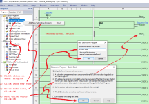
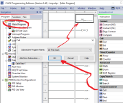
Create a subroutine like this. The rungs in a subroutine are executed as if those same rungs had been inserted into the Main Program at any and all rungs that call that subroutine.
Untitled2.png

Call the subroutine from the [Main Program] like this. N.B. this subroutine call is made unconditionally; @OkiePC's example uses a conditional subroutine call.
Untitled3.png
 
Remember that PLC programming is about time, and the scan cycle is the fundamental "unit" of time.

The rungs in the Main Program are executed top rung/branch to bottom and left to right on the rung/branch, once per scan cycle, and that scan cycle is repeated continuously. So any subroutines called from the Main Program are also called continuously.

The canonical subroutine gotcha: if a subroutine is not called from the Main Program, then that subroutine's rungs are not executed; a story that has been repeated many times on this forum is someone posting code and asking why it is not executing, only to realize that the subroutine, in which that code resides, is not being called.
 
  • finally, rung 23 will always reset the value of <ds1 seq step> to 0, whenever <ds1 seq step> is not 10, so this code will never be at [ds1 seq step=20] on any scan after rung 23, nor will it ever start any scan at [ds1 seq step=20].
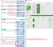
Here is a sample program demonstrating that the sequence step will never reach 20:
Untitled.png
 

Similar Topics

Hello. I have been trying to crack this one without success and could not find any hint after several search attempts. I wonder if any CODESYS...
Replies
4
Views
3,920
Hello, I'm pretty sure I know the answer to this, but wanted to verify with the experts. Am I able to write a program using the Micro Starter...
Replies
7
Views
3,151
First off, i am new to ladder logic. I do have some experience programming microcontrollers in C. I will try and give a short version and if more...
Replies
7
Views
2,011
This is a CompactLogix L33ERM, version 30 (31 is too unstable on my machine to work with), with a Kinetix 5500 drive. I have a program where...
Replies
2
Views
2,000
Good morning guys! I have a doubt. I uploaded a program from a S7-200xp on the field and took it to the office. Before doing any test I tried to...
Replies
7
Views
2,153
Back
Top Bottom