You are using an out of date browser. It may not display this or other websites correctly.
You should upgrade or use an alternative browser.
You should upgrade or use an alternative browser.
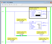
Micrologix 1100- Can't get STI to work
- Thread starter akanov
- Start date
Ken Roach
Lifetime Supporting Member + Moderator
Welcome to the PLCTalk forum community !
CTU instructions require a rung condition that transitions from False to True in order to increment.
You could use an ADD instruction in its place to prove out the functioning of your STI; an ADD executes every time the rung is scanned and the preconditions are true.
CTU instructions require a rung condition that transitions from False to True in order to increment.
You could use an ADD instruction in its place to prove out the functioning of your STI; an ADD executes every time the rung is scanned and the preconditions are true.
kamenges
Member
Two thoughts come to mind.
I'm not sure if this will work but you could try to unlatch the BSL enable bit immediately after the instruction executes. This might make it look to the instruction like it wasn't active last scan and cause it to execute. As I said, this might not work right. You are basically trying to trick the instruction, which may or may not be viable.
The other, more "acceptable" way to do this would be to change your STI call rate from 1000 msec to 500 msec. Add a rung on the bottom of the routine that is a self-toggle:
XIO(Toggle) OTE(Toggle)
This will change the Toggle bit status every STI run. Use an XIC of Toggle in both the BSL and CTU rungs. You will get the same time performance but you will also get the rung status change you need to make them work.
Keith
drbitboy
Lifetime Supporting Member
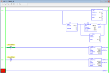
I'll probably get six kinds of grief for suggesting this, and deserve it, but it is a smaller change to your original program; see the image below.
Specifically, I extended the branch with the CTU in it, inserting this:
You can probably do summat similar with the BSL.
Even if it works, it only demonstrates what Ken said about CTUs needing a rung False=>True transition, and we should never fiddle with the internals of compound instructions like a counter.

Specifically, I extended the branch with the CTU in it, inserting this:
Code:
NXB XIO C5:1/DN OTU C5:1/CUEven if it works, it only demonstrates what Ken said about CTUs needing a rung False=>True transition, and we should never fiddle with the internals of compound instructions like a counter.

Last edited:
drbitboy
Lifetime Supporting Member
[d'Oh! kamenges suggested this half an hour ago, while I was fiddling with the CTU internals]
How about every other interrupt, but you run the STI twice as often:
1) Go back to your original code
1.1) Set the STI time to 500ms
2) Add a bit that toggles on every pass through the STI e.g.
2.1) That bit will have a rising edge (Ken's [False=>True] transition) once per second i.e. every other STI pass.
3) Put an XIC on that bit on the rungs in front of your BSL and your CTU; the rising edge of that XIC will trigger the BSL and CTU to shift and count, respectively, every 1000ms (= 500ms + 500ms).
It's kludgy, but it will work.
Thank you Ken,
Using ADD worked. I still have a problem with the first BSL though. looks like it too needs a condition that alternates true/false.
Do you have any suggestion how to make it shift at every interrupt?
Thanks again
How about every other interrupt, but you run the STI twice as often:
1) Go back to your original code
1.1) Set the STI time to 500ms
2) Add a bit that toggles on every pass through the STI e.g.
Code:
 B3:0/13  B3:0/13
---]/[------( )---3) Put an XIC on that bit on the rungs in front of your BSL and your CTU; the rising edge of that XIC will trigger the BSL and CTU to shift and count, respectively, every 1000ms (= 500ms + 500ms).
It's kludgy, but it will work.
Last edited:
Thank you all,
My first post here and you have been amazing!
Last time I wrote a program it was 2010- a little rusty but it is all coming back.
On the picture above I set the interrupt time to 1000 ms to be able to visually confirm the subroutine is executed. In reality I am tracking a product on conveyor line and I was aiming at 2 ms for STI. now with the need to call it 2 times to get one bit shift it becomes 4 ms for the bit shift. Not ideal but still OK.
I tried to set STI at 1 ms however then the cycle time skyrocketed to 1-2 seconds (from 2-5 ms)
Thanks again
You could instead get the CTU & BSL to trigger every scan by duplicating the rung/branch and having one triggered by an XIC of the toggle bit, the other by an XIO. This would remove the need to run it twice as often.
Last edited:
drbitboy
Lifetime Supporting Member
You could instead get the CTU & BSL to trigger every scan by duplicating the rung/branch and having one triggered by an XIC of the toggle bit, the other by an XIO. This would remove the need to run it twice as often.
Sweet!
kamenges
Member
That idea would work with the BSL, which has its control structure (R-file) separate from the data structure (B-file). It wouldn't work with the CTU if a common counter number is used since the control structure and data structure are combined into a single element (C-file). It is the control structure that needs to see the change in state. The instruction is just a way to access the control structure so simply adding another instruction isn't going to get you anywhere.
Keith
EDIT: I stand corrected.
EDIT #2: If you are using an ALWAYS_ON with the the two states on one instruction data set you are doing basically what drbitboy shows in his rung snip. You are setting the control structure enables to OFF immediately after you turn them on.
Keith
EDIT: I stand corrected.
EDIT #2: If you are using an ALWAYS_ON with the the two states on one instruction data set you are doing basically what drbitboy shows in his rung snip. You are setting the control structure enables to OFF immediately after you turn them on.
Last edited:
Ken Roach
Lifetime Supporting Member + Moderator
Why do you need to run a large bit shift every 2 milliseconds ?
In general, if you need to react quickly to an input, use a Discrete Input Interrupt, not a Selectable Timed Interrupt.
It sounds like you're trying to create a bit array that's full of 1's when a photoeye input is true. Are you trying to measure a package by counting the 1's in an array, rather than using timers or timetstamps or encoder counts ?
Ken,
The application is a finger diverter- similar to this one (our previous model):
https://www.youtube.com/watch?v=eUbvgvFmE_g
I am tracking the products with BSL (creating digital "ghost" image) to determine when to fire the fingers and to flag the ones to be rejected. This way I eliminate completely the use of timers in RUN mode (and just two in teach mode)
At the desired conveyor speed the product travels 1mm in 2ms.
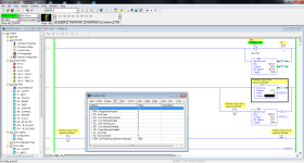
Here is the finished STI subroutine that works great (at 2 ms) and was written based on all the above comments:

drbitboy
Lifetime Supporting Member
too cool.
run that youtube at 0.25 real-time.
run that youtube at 0.25 real-time.
Ken Roach
Lifetime Supporting Member + Moderator
Very cool ! A fast finger diverter is exactly the sort of application where an encoder, STI, or DII feature in the MicroLogix might be very useful.
Good luck !
Good luck !
Similar Topics
Hi,
I cannot find the DLCA1764.EXE utilty software for data retrieving. Can someone share the link to download this software. Thanks!
- Replies
- 4
- Views
- 113
I am currently backing a Micro Logix 1100 and no-one seems to have the file for me to upload from. Is there a way for me to upload the project off...
- Replies
- 15
- Views
- 510
I am trying to set up a read message in a MicroLogix1100 to read the value of a DINT in a ControlLogix5561. I have successfully set up a message...
- Replies
- 2
- Views
- 187
Hello,
I have an existing application that has a Powerflex 700 with a 20-COMM-E adapter controlled by a Micrologix 1100 via Ethernet. The setup...
- Replies
- 6
- Views
- 1,192
I have a MicroLogix 1100 and it's capable of ac or dc output voltages. What I don't know is how I'm supposed to tell the 1100 to use dc for the...
- Replies
- 13
- Views
- 1,403


