Fischer Porter Flowmeter

OkiePC

Lifetime Supporting Member
Join Date
Mar 2005
Location
ENE of Nowhere Oklahoma
Posts
11,790
My experience with this type of flowmeter is limited.

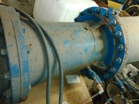
I am not sure if this is a venturi or some other type.

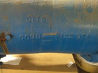
It has a data plate and we have a call in to ABB who bought the old company who made it to try to get information about it.

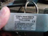
The DP transmitter has failed. It is not the original transmitter, but a cheap replacement installed many years ago. The plant operator has ordered an identical replacement as a first step.

I wanted to verify the logic in the PLC that is used to convert the DP to flow rate, but I inherited the logic without comments so I am not certain it was done right, not sure if the logic matches the transmitter. The only other two times I have worked on this type of transmitter, in both cases the PLC logic was not even close to correct.

The pipe is supposed to be 20" diameter. The fluid is gravity fed water from a storage tank about 55' of head. This is a backwash flow line for a rapid gravity filter.

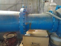
The 2nd picture shows the ports used by the DP transmitter at the bottom right in the frame. The port on top appears to be routed to an old pressure sensor that has been abandoned.

Can someone help me identify first the type of meter this is and guide me to some links to the math? I will post snippets of the PLC logic later.

Thanks!
KIMG0159.jpg KIMG0160.jpg KIMG0162.jpg KIMG0153.jpg
 
Last edited:
Logic attached (pdf report)

The data plate on the venturi:

Fischer Porter
Model 10F1082
TH.I.D.11.371 IN.

The "F" might be "E". The last line may have some significance for someone who deals with these things.
 
Last edited:
Just get a replacement with the same specs. If you can shut of the water from the tank then just do this, read the level of the tank and let water on again for a specified time and do a reading on the analog signal.
Then just read the level of the tank again and calculate how much water has gone out, and then calculate the flow and compare to the PLC.

We do have a level transmitter from the tank and I believe a drawing exists from which I can calculate volume. If I can verify the accuracy of that level transmitter, your method may work well. I believe the tank is filled automatically from a pressure operated valve, so so I may not be able to rely on calculations from level all the time, but perhaps we can isolate it for some tests to at least verify the new transmitter and logic when it is installed.
 
It's obviously a DP flowmeter

proprietary_flow_tubes.jpg


It appears that the high side tap is right on the high side flange, like the Badger in the diagram.

A 0-50psid DP transmitter seems like a a mismatched transmitter. The range is too high. Working DP's are typically nowhere near that range. The transmitter be turned way down.

If you're looking at all for any 'accuracy', you can hope that ABB kept the original 'sizing' data from when it was originally manufactured.

That info boils down to a max DP (say 72.37" wc) at max flow rate of 300 gpm, which is what you need to correctly range a DP transmitter.

Without that info, it's guesstimation time.
 
It's obviously a DP flowmeter

Yep. I am glad you chimed in, Dan. I am novice with these old things, and I was not sure what kind...venturi, orifice plate or some hybrid...

A 0-50psid DP transmitter seems like a a mismatched transmitter. The range is too high. Working DP's are typically nowhere near that range. The transmitter be turned way down.

I thought the same thing. This is a big pipe and the flow according to the operator, could be much more than the 3040 gpm it reads now. It reads 3040 gpm now (even with the valve closed) because the old transmitter puts out 6.4mA no matter what you do to it. I did get 14mA out of it by venting the low side, but with both ports open to air, it puts out 6mA

If you're looking at all for any 'accuracy', you can hope that ABB kept the original 'sizing' data from when it was originally manufactured.

That info boils down to a max DP (say 72.37" wc) at max flow rate of 300 gpm, which is what you need to correctly range a DP transmitter.

Without that info, it's guesstimation time.

We're awaiting word from them (ABB) on it. We may end up with not much more than a good guess, and if the operators want better accuracy, we may be able to sell them a new ultrasonic or something along those lines.

I think the numbers you gave are purely for illustration, right? The DP value I expected was much much less than 50PSID. The other two (orifice plate DP) I have worked on were 100"h2o and 50"h2o and one of them was in a 30" pipe.
 
Last edited:
For sure it is a venturi type, though orifice plate types also follow the same flow ~ sqrt(dP) relation of post #2. The most direct way to scale it is to run an in-place calibration, as suggested in post #3. Since you have a tank w/ level detector, that might be easy if you can afford to run flow tests. Try to get at least 10 points on the flow curve and try fitting a sqrt function. Excel's Solver add-in lets you fit any function by a trial and error search for best-fit coefficients, and you don't have to limit yourself to a sqrt relation.

If you can't run actual flow calibrations, you can calculate the dP vs flow response from "first principles". A text "Flowmeter Engineering" documents this. Yours might be an "ASME machined venturi", which has Cd = 0.995, for certain Reynold's numbers (see ASME Standard MFC-3M-1989). If you can assume incompressible (water, etc), the equation is simple, but you will have to know throat diameter. When the density changes, it gets complicated, and requires temperature and line pressure sensors. If you have thermodynamic relations (ex. in NIST 5.0 software), you can use the enthalpy change to get throat velocity [dh = d(v^2)/2], assuming isentropic flow. We use that method in rocket propulsion testing. For those using gases, the "Y factor" is an older approach that works for almost ideal gases (low pressure), but the enthalpy method is always exact and often simpler. Of course, these approaches require understanding unit conversion and such, so requires a competent degreed engineer. If you can run flow tests that is easier and more assured.
 
It is not the original (DP) transmitter, but a cheap replacement installed many years ago. The plant operator has ordered an identical replacement as a first step.
Stop the replacement order until you find out what the range is. Most DP uses a 0-15psi/0-400"wc/0-100kPa range transmitter since that fits most DP primary flow elements, but without the factory number, it's hard to say.

The numbers I stated previously were out-of-the-blue. Orifice plates can be bored for either a round number DP (100"wc) or a round number max flow (3,000gpm). Fabricated primary flow elements typically are 'sized' (calculation run for) an even flow rate at some oddball DP: 121.74"wc at 3000 gpm (fake example).

The bigger issue is that even with the correct DP/flow rate, this is NOT an application for an "accurate" DP flow meter.

DP accuracy is related to 'design conditions'. The design conditions (for cold water) are essentially static pressure (upstream pressure P1), (the temperature of (incompressible) water has little influence). The more P1 changes from design conditions, the greater the deviation, the greater the error.

The fluid is gravity fed water from a storage tank about 55' of head.
Unless I've missed something, a gravity fed flow meter will always have a varying P1, depending on the tank level. So that the output will almost never be at design conditions, but will have an error due to P1 deviation from design conditions.

I hope that the original sizing picked some mid-tank level value for the P1 static pressure value in order to put the error somewhere in the middle of the tank level, instead of always low or always high error.

If it's a case of "have to use what's there" or they've lived with the error for 30 years and are willing to live with it for another 20, then using the factory data should work. In clean water service the element is probably still in pretty good shape. But you need a transmitter with a range close to to what the element is producing.

Those old analog (non-smart) DPs drifted about 1% per quarter, 4%/year. So your 2 mA offset is just reflective of 12.5% drift, probably the drift limit, if it's even still functional. There might be a zero adjust pot on it, but it's still likely the wrong range for the element.

routed to an old pressure sensor that has been abandoned.
If the original DP is there, you might look for a tag on it spec'ing the URV (upper range value) that it was calibrated/ranged at. That's half the info you're looking for from the factory, the other half is, that DP represents what flow rate.

I wanted to verify the logic in the PLC that is used to convert the DP to flow rate, but I inherited the logic without comments so I am not certain it was done right, not sure if the logic matches the transmitter. The only other two times I have worked on this type of transmitter, in both cases the PLC logic was not even close to correct.

You're showing your age (and experience). How true.

If replacing, a clamp-on ultrasonic transit time flow meter or an insertion magnetic flow meter would easily handle the flow.

Dan
 
I would probably be happy with the existing venturi meter. They can be very accurate under certain conditions. The biggest issue is that the measured flow-rate should stay on the upper 50% of range. Since the dP signal varies with the square of the flow-rate, at 25% max flow, the dP signal is only 6.3% of max. As mentioned, you also want to size the dP xducer range close to max expected signal (as for all sensors).

Another issue is that most dP xducers suffer a zero shift with line pressure. It seems that is the issue danw refers to regarding at what tank level the signal was scaled. But, modern quality dP xducers often spec <0.5% of dP range shift per 1000 psig line pressure change, especially Yokogawa, Fuji and other process plant types (not cheap) . Your 55' level change gives only 22 psi line shift max, so a negligible issue. Of course, one can correct for line pressure shift, if you run tests to characterize it. We did so in one setup, but several xducers we tested also showed much hysteresis (can't be compensated). In that case, our line pressure varied ~6000 psig during a test. Of course, even if line pressure is high, if it doesn't vary you can tare the xducer signal with no flow to compensate. Another concern with line pressure is that the water doesn't cavitate at the throat, but unlikely even at the lowest tank level unless it is very hot.

If you do run flow tests, that may not be as simple as it seems. At high tank outflows, the level might not be horizontal, due to a vortex. In the worst-case, this can even entrain air into the flow thru the venturi. When the Saturn V rocket injectors were flow-tested in the 1960's, using a "dump flow into large tank against stopwatch" method, they used load-cells to weigh the liquid in the tank, probably because trying to measure a sloshing level proved too difficult.

In our industry, we can't always do in-place flow calibrations, so often rely on venturi calculations from first principles. That works best when you are setup for it with bonded software and spreadsheets, based on validated methods. Most flowmeter manufacturers would have that, but it can become a mini "science project" for engineers in the field.
 
Last edited:
Here is a link to a company that makes venturi tubes.
http://www.imperialco.net/venturi/venturi.html#Venturi p29.

The last page lists capacities and dimensions. You can see the 20" venturi has a throat diameter of 11.55" ,very close to yours.You can get a rough idea of the flow rates and resulting differential pressures. You also should have at least 6 pipe diameters upstream of straight pipe so that the flow is laminar at the throat. A clamp on transit time ultrasonic flowmeter is not accurate because of the concrete lining in ductile iron pipe attenuates the signal. ( full disclosure, it has been over ten years since i messed with one.).

The plant should have a set of documentation furnished when the job was complete. Check for the submittal drawings for the venturi. It should give you a differential pressure for a maximum flow rate. It might even have the calibration tables for the flowmeter. The design engineer should also have the same documentation.
If all that fails, I have successfully used these to take the place of the venturi. https://www.armstronginternational....ow-measurement/veris-flow-measurement/verabar.
 
I sure do appreciate all of you taking the time to help me with such detailed answers. It may be some time before I get to the bottom of this problem, since it is NOT what I came up here to work on. I have to get finished up with some chemical feed programming and commissioning by day's end, and we will dig into the backwash flow when we have a bow on the other half dozen details we have ourselves engaged in at the moment.

Thanks so much...
Paul
 
I would guess that the badger style meter is what this may be. In one of your pictures, it appears that the 20" pipe is reduced down with a long reducer to the meter inlet. If that is so, It would appear that Diameter1 is not equal to 20".

Here are some helpful links.
http://www.engineeringtoolbox.com/flow-meters-d_493.html
http://www.engineeringtoolbox.com/orifice-nozzle-venturi-d_590.html
http://www.engineeringtoolbox.com/water-density-specific-weight-d_595.html

The theoretical flow can be calculated as
q=A2[2(deltaP)/rho(A2/A1)^2]^(1/2)
where
deltaP=p1-p2
A1=upstream area
A2=downstream area
rho=density
 

Similar Topics

X
I'm trying to come up with a small DCS system based upon a Fischer-Porter system. System consists of a supervisory PC Op Station with 10 PID...
Replies
4
Views
3,741
Xeones
X
Hi guys; Any one know how to use Matrikon server and excell reporter with GE plc 90-30 series; I need guide line how to configure it to read and...
Replies
3
Views
1,827
Hi, I'm working as an engineer for a factory. Our electrical network contains more than hundred measurement point. We use Schneider-Electric...
Replies
3
Views
2,130
I can not get XLreporter 7.0 of the License, please tell me a permanent KEY.THINKS
Replies
1
Views
2,794
Hi there, Anybody got any step by step information on setting up excell reports using this add in software? I am using RS LINX OPC server...
Replies
0
Views
2,170
Back
Top Bottom