Msg instruction path help

priceymike

Member
Join Date
Feb 2016
Location
london
Posts
5
Hi,
I'm trying to ensure I have the correct path to allow msg read from 5380 processor via compactlogix. The SI has installed it in a way I'm not familiar with, the Processor is connected to network via an Ethernet card not mounted in back plain.

Can I msg directly to 5380 with localENB, 2, 10.178.244.112, 1 , 0. Or do I need to go through the Ethernet card which is 10.178.244.113.

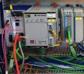
Picture attached, the route goes Hirsch man switch , ethernet card port 2, port 1 to PLC.

Many thanks
 
Hi priceymike,

Your picture hasn't come through.

I don't think you need the 1,0 on the end, as the ethernet port is embedded into the 5380. That last "hop" is typically for when the comms module is separate from the processor, and the path needs to specify "go out to the backplane" (1), then go to slot 0 (0). Most often seen in ControlLogix paths using an Ethernet module in a separate slot.

Is the 5380 in your I/O configuration ? (It would need to be if you were doing any produced/consumed tags).
 
Last edited:
If you are in any doubt, you can (if it isn't there already), just add the remote controller into the I/O configuration, and then in your MSG Path field just use its name.

You already have the local_ENB in the I/O, just put the remote controller under it.
 
Hi Daba,

Thanks for your info, I'll try without the 0,1.

The 5380 is not in the IO from the PLC I want to read to, This can only be done with a download I believe, which is something I cannot do at this time.

Picture here.

https://ibb.co/rttN1Tz
 
Mostly you can add IO devices online.

Some Ethernet devices, and probably your 5380, can't be.

Just try it, and if it's greyed out, you can't.

If you can, be aware that it pulls on network traffic a touch, so don't do it if you have any high-speed motion control going on, for example. You get a warning about this.
 
Last edited:
I was surprised by the photograph; thank you for posting it.

Your OEM used a newest-platform 5380 series CompactLogix, but connected it to the classic-platform 1769 series I/O modules using a 1769-AENTR adapter instead of using 5069 series I/O, which would have connected to the controller directly.

The Hirschmann RS20 switch has a different kind of ring protocol than the Rockwell "Device Level Ring", so your OEM didn't use a network ring, just a daisy-chain of devices. They used only one port of the 5380 CompactLogix.

The advice you've received is correct: the end-point of the MSG instruction should be the IP address of the CompactLogix 5380 controller itself.

You don't need to add a "1,0" like with older CompactLogix, and the IP address of that 1769-AENTR is not involved in the MSG instruction.

Logix5380_with_AENT.png
 
Ken, I just tried to do a Read from a 5380 to a older L35E. "2, IP" at as path didn't work so I had to add the L35 in the IO tree and it worked.

What did I miss? does it need to "2, IP, LocalENB, 1,0"?
 
For exposition, note that Harry's question involves different controllers than Mike's original question.

The first-generation CompactLogix 1769-L32E and 1769-L35E emulated the ControlLogix backplane with a "backplane object".

Messaging-wise, you treat those controllers like a 1756 ControlLogix with a CPU in Slot 0 and a 1756-ENBT in Slot 1.

Putting the 1769-L35E into the I/O tree tells Studio 5000 about its architecture, and if you were going to hard-code the CIP Path you would use "2, [IP], 1, 0".


The 5370 and 5380 series CompactLogix consider the Ethernet module and the CPU module to be in the same module. The CIP Path ends at the IP address itself.

I don't think it hurts to add a "1, 0" at the end of the CIP path; the controller knows what to do with that message.
 
Message "Path" rules.

For anyone who finds configuring a message path difficult, there is a simple rule to follow, which always works.

Just keep repeating the pair of specifications....

Port, Destination [, Port, Destination]

....until you have completed the "journey".

A simple example, suppose I have a ControLogix controller in my chassis (doesn't matter what slot it is in), and a comms module in slot 5, and I want to Read from, or Write to, another ControlLogix controller in slot 8 of a remote chassis, with a similar comms module in any slot.

Now, the first pair of path parameters will define how we leave our controller, in our case we have to go onto the 1756 backplane, and for any module that is always Port 1. Once on the backplane, we want to go to the comms module in slot 5. So we have....

1, 5, ..... as the start of our path.

From the comms module we want to come out of the primary comms port, which is port 2 (port 1 is the backplane port), and go to our destination address, whatever that is. For Ethernet the destination address will be the IP address, and for DeviceNet or ControlNet it will be the Node address.

Say our remote Ethernet module has the IP address 192.168.1.67, then the second pair of path parameters, added on to the first pair, makes our path now...

1, 5, 2, 192.168.1.67,....

Now we have landed in our remote comms module, so we have to go out onto the backplane of the remote chassis Port 1), and our destination will be the slot number of the remote controller (slot 8). The path to the remote controller is then complete, being ....

1, 5, 2, 192.168.1.67, 1, 8

There will always be an even number of parameters, unless part or all of that path is already defined, which occurs if any part of the path is included in the I/O configuration, e.g. If I have my local 1756-EN2T comms module in the I/O config called "local_EN2T", then that name replaces the first pair of parameters ....

local_EN2T, 2, 192.168.1.67, 1, 8

and if I have the remote Ethernet module (as a child to local_EN2T) in the I/O configuration named "remote_EN2T", then that name replaces the part of the path, because it is already defined ....

remote_EN2T, 1, 8

if the remote controller is then added as a child to the remote Ethernet module, and we call it "remote_CLX", then our path can be entered simply as ....

remote_CLX

In fact we wouldn't enter it, we can simply choose it from a drop-down list, the same goes for any preceding path segments. Any named modules in the I/O configuration will appear in the drop-down list.

Now for the clever part. As we start to enter our path specification (Port, Dest, ...), then the software will echo (underneath the entry field) when it is a valid path segment. It does not mean the path is complete, it just means that, up to now, the path is valid.

So if I type 1,5 then either it will echo 1,5 under the entry field, or it will pop-up the name of the module at 1,5 e.g. "local_ENBT". As we continue to build our path, the echo will disappear, reappear, disappear, reappear, as each complete "hop" is added to the path, always replacing your [Port, Dest] pairs of specifications with the actual path-name, if it is known.

Long post, I know, but if you just remember [Port, Dest] repeated until you land in the target module you will not go wrong.


Once I started thinking about the parts of message paths in pairs, it became a lot easier to figure it out. This is a great post that should put it plainly for anyone who's having issues figuring it out.
 
Going on from my rather long post above, some might say "Why not just put all the modules you want to message with into the I/O configuration, and choose the paths from the drop-down list?"

The answer is that it creates a permanent "Connection" for each device, and the number of "Connections" you can have is finite, mostly determined by the comms modules.

Remote I/O consumes permanent connections as well as messages, and each connection is additional network traffic you may not want. So if you had a lot of remote controllers, and were reading production data from them once a day, for example, then you may not have enough connections available to you.

Messages usually create a temporary connection, taken from the pool of available connections, perform the data transfer, then close the connection, keeping network traffic to a minimum, and boosting performance. Messages can, however, have a "cached" connection if you so desire, keeping the connection established permanently, and the messages will execute slightly faster. I have never used a cached connection, never had the need to.
 
Once I started thinking about the parts of message paths in pairs, it became a lot easier to figure it out. This is a great post that should put it plainly for anyone who's having issues figuring it out.


Glad it helped you ....
 
Thank you Daba for you help, I set the path without the 1, 0 and it still didn't work......due to the 5380 having a typo in the tag I was reading once that was corrected I was up and running.
The 5380 isn't a part used anywhere else on our sites and has been provided by the plant manufacturer instead of there usual Siemens PLCs so we have the ability to easily take signals across the site network, allow mapping to telemetry points for viewing on our regional scada system.
They have written the code in structured text which does 2 things for them, one stops us more familiar with ladder understanding it and two as this makes standardising code between Siemens and Allen Bradley easier.
Thanks all for sharing your knowledge, I've got plenty more of this to do on out plants.
Mike
 

Similar Topics

Hello, I am using a Compactlogix 5380 PLC and need to read values from a few existing PLC 5s, other Compactlogix PLCss, and a few Controllogix...
Replies
10
Views
4,155
In Studio 5000 is there any way to change the path for a MESSAGE datatype during runtime? I want to be able to set the same Path(IP address)...
Replies
21
Views
6,422
I can't seem to figure out this path format for the new controllers, especially since there are two ethernet networks. Does anyone know the format...
Replies
9
Views
10,423
Hello All, I am trying to set up an RSLogix 5000 program to email me once a certain condition exists. I believe I have everything else set up...
Replies
0
Views
1,547
I have a question, on the MSG instruction communication path setting. I would like to read an analog controller, 5555 to the 5561 controller, two...
Replies
9
Views
56,410
Back
Top Bottom