Multimeter question. Resistance and voltage

SPL Tech

Member
Join Date
Nov 2011
Location
new york
Posts
9
So the other day I took a 9V battery, an analog multimeter, a digital multimeter and a 1M ohm resister and I did an experiment. First I tested the voltage of the battery with both multimeters. Both read 9.6v. Then I took the 1M ohm resister and put it on the positive battery terminal. Next I put the analog multimeter in series. It read about 0.1V. Then I took the digital multimeter and repeated the exercise. It read 9.6v. My question is why? It is my understanding that resistance reduces voltage, not just current, so why would the digital multimeter give me the same voltage reading regardless of the resistance in series with it? I tried numerous other resistors and they all affected the analog meter, but not the digital meter. I tried a second true RMS multimeter and came up with the same results.
 
Last edited:
You are only allowing 0.0000096A to flow through the avo meter(moving coil) analogue multimeter not enough to get the deflection. The digital has a high impedance to its op amp and 0.0000096 is enough to measure volts. Interesting now try with the resistor in parallel with the battery.
 
Multimeters should not effect the circuit load. so they do not add any resistance to the testing cct. this is especially so with digital meters.
If you check the voltage of an open circuit, there is no flowing current so no voltage drop should be present and the result is 9.6V
try 'rigicon''s suggestion or even try two 100 ohm resistors in series.
you should see about 4.8 volts across either one of the resistors.
 
when you get this experiment completely worked out you'll have the answer to an age-old question:

why does a PLC TRIAC-type output module give an ON (full voltage) reading when being checked with a sensitive (digital-type) voltmeter – even when the output's bit/box contains an OFF status of ZERO? ...

on the other hand, checking the same OFF output circuit will give a LOWER reading (something like 70 volts) when checked with many analog-type meters ...

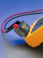
if you need to work with this type of stuff in the field, you might want to take a look at the Fluke Stray Voltage Adapter part number SV225 ...

http://en-us.fluke.com/products/acc...ef=/products/all-accessories#fbid=a8o7gW5Qq_S

.

sv225.jpg
 
Last edited:
Maybe I'm wrong but when you are mesuring voltage with a meter you are mesuring the voltage drop across that circuit. So with an open circuit weather you have a resister in series or not you are still dropping 9.6 volts across the meter. If you completed the circuit and put the meter leads across the resister esentially putting the meter in parallel as previously stated you will read the voltage drop across the resister.
 
Most digital multimeters have built in resistors in the 10M ohm range to protect them from current flow, so by adding the 1M ohm resistor you only increased resistance by 10%.

I am not old enough to know if the analog multimeter has resistors built in or not lol.
 
I am not old enough to know if the analog multimeter has resistors built in or not lol.

I prefer to say I'm experienced. :D

Yes, analog meters have (had) resistors in them. They were in series with the meter movement. Depending on the sensitivity of the movement the input impedance is (was) much lower than a digital meter which might be 10Mohm or more. Also input impedance varied with the voltage range selected.

The venerable Simpson 260 had an input impedance of 20Kohm/volt, I believe. So on the 10 volt range. It would only be 200Kohm. So, you would essentially have a 200Kohm resistance in series with your 1Mohm resistor. So, your resistor would drop 8.0 volts and the Simpson would only see the remaining 1.6 volts.

So, what happens when you change voltage ranges on the analog meter?
 
Analogue meter: Current through circuit = 9.5 / 1000 000 = 9.5 * 10^-6 Amp.
Meter resistance = 0.1 / 9.5 * 10^-6 = 10526 ohms or about 10 000 ohms.

Digital meter: The voltage across the 1M ohm resistor will not be zero. For the purposes of the illustration lets say the voltage across the resistor is 0.1 volt then the meter reading would be 9.5 volts.
Current through circuit would then be 0.1 / 1 * 1000 000 = 1 * 10^-7 amp.
Meter resistance = 9.5 / 1 * 10^-7 = 95 000 000 ohms say 100 M ohms.

So you see that the digital meter has a much higher input impedance than the analogue meter. That is why you get the readings that you have observed.

The digital meter is similar to the "Valve voltmeters" used in the early days of electronics.

One should be careful when interpreting readings from different types of meters as they can be misleading sometimes.
 
Last edited:
Know your meter. (y)

Everything that have moving needle aren't low input impedance meters (ie. I have one old "analog meter" with 100Mohm input impedance in D.C 1mV range as it's FET chopper amplified)

Everything that have digital display do not have high input impedance. (ie. cheap chinese meters could have 1Mohm input, like my first DMM)

In analog meters the Ohm/V value is typically printed near the scales or down corners of the meter face.

If I understood correctly how you did connect the meters you created a voltage divider circuit. In your analogue meter the input impedance is much smaller than the 1Mohm resistor I believe. DMM it seems you have a lot of input impedance.

Resistance reduces current,it doesn't reduce voltage it divides it o_O

Edit. PS. It too late time of day for me to make any maths, but if Calistodwt is calculating your meters input impedances (meter resistance) correctly. Try to put one 100Meg.Ohms resistor in the place of your current 1Meg.Ohms. resistor. The reading of your DMM should be about 4.8 Volts. Same goes to Analog meter if you replace the resistor of 1Mohms. with 10kOhms. you should have readings of about 4.9 Volts if I'm not terribly mistaken.

R1
+-----------I===I-----+------ Vout
| |
___ | |
- Vin (9.6Volts) | | R2 (meter impedance)
| case |
+---------------------+ Vout=Vin*(R2/(R1+R2))


Btw. There is these same quirks when measuring currents, they are different but still there.
🍻
 
Last edited:
I prefer to say I'm experienced. :D

Yes, analog meters have (had) resistors in them. They were in series with the meter movement. Depending on the sensitivity of the movement the input impedance is (was) much lower than a digital meter which might be 10Mohm or more. Also input impedance varied with the voltage range selected.

The venerable Simpson 260 had an input impedance of 20Kohm/volt, I believe. So on the 10 volt range. It would only be 200Kohm. So, you would essentially have a 200Kohm resistance in series with your 1Mohm resistor. So, your resistor would drop 8.0 volts and the Simpson would only see the remaining 1.6 volts.

So, what happens when you change voltage ranges on the analog meter?

The best one I ever saw (when I was in the RAAF in the 80's), had a sensitivity of 500k/volt. Meaning that say on the 100v scale, it had an input impedance of 50Mohm. I believe my Fluke 87 has a fixed input impedance of 10Mohm.
 

Similar Topics

I did a search and came across a post about comparing meter brands, but id like to have a discussion about what meter you carry, and why. Im...
Replies
58
Views
15,203
Ok, So I'm looking to purchase a new meter to replace my current one. What I'm looking for may not exist, but please let me know if it does or...
Replies
10
Views
4,517
A bit off topic but I know this esteem group would have opinions on this subject. We are having a debate concerning multimeter calibrations. We...
Replies
10
Views
3,802
I am currently working with a 1769-L32E processor and a 34410a Agilent Multimeter. We need to send the meter a MSG command telling it to take the...
Replies
5
Views
1,833
HI i would like to know how to get a variable that will store the amount of times a program has been executed. The issue is I have 3 DBs for 1 FB...
Replies
2
Views
45
Back
Top Bottom