Controlling a valve with backlash

aley

Member
Join Date
Jun 2014
Location
Albuquerque, NM
Posts
10
TL;DR I'm trying to control a valve that has some backlash - what's the best way to control this based on flow sensor output?

I've got a valve for process water. Historically, it's been controlled with a knob; the operators walk up to the equipment, look at what's coming out, think, "This should be a little wetter," and open the valve a bit more. That's been the plant standard for 38 years, but really wasn't good enough in 1982 when the plant was built, and sure isn't good enough now.

As part of a controls redo (I've replaced the 1982-vintage relay logic with a Micrologix 1400) I've put in a water valve controlled by an analog output from the PLC (Valworx 565467A), and I've added a flow sensor (Keyence FD-Q20C) on an analog input. Now I'm trying to close the control loop.

My issue is that there's some backlash in the valve. The backlash in the region where our process usually runs is around 10%; I haven't measured it elsewhere, but it's probably not too far off that across the board.

My first thought had been to put in a PID loop, using the 4-20mA signal from the FD-Q20C as the process variable and the valve position as the control variable. All my experience with PIDs has been with heaters, though, where backlash isn't a factor. It seems like I'm going to get wild oscillations with the valve and its backlash, and even if I can tune the loop to provide acceptable control I'll end up with the valve opening and closing a lot more than it should have to. I've thought about adding some code to make sure the valve is always on the same side of the backlash, but this will slow the process down quite a bit and may not do much to solve the issue.

I've been thinking that I might do better to roll my own control loop - for instance, upon the user changing the setpoint on the HMI, I could move the valve to a position based on a lookup table (approximate correct position), then add the error in flow rate back into the valve position to drive it toward the correct value, perhaps with different coefficients depending on whether the error is positive or negative so that it will quickly cross the backlash, overshoot, then slowly come back toward the correct setpoint. Seems like a good way to have the valve hunt for position, though, which is going to wear out the actuator mechanism sooner.

Any suggestions? I'm sure I'm not the only one who's ever faced controlling a system with backlash, and somebody's already figured out more good ways to do it than I'll ever come up with.
 
When you say “backlash” are you talking about the fact that the full port ball valve is not linear for flow control or some kind of valve linkage “slop”?

A ball valve can be a pain to get tuned in especially if flow requirements change a lot. A V Port ball valve will give you way more linearity for control.

Welcom to the Fourm!!
 
The backlash I'm referring to is mechanical slop in the system. I haven't looked to see where the slop is coming from, but probably a combination of play in the gears of the motor and clearance between the valve itself and the gearmotor output shaft.

I chose the ball valve more based on simplicity and the fact that we've got quite a few Valworx valves around the plant that all work well in our dusty environment; I hadn't really considered nonlinearity to be an issue, since the plan was always to have a flowmeter for feedback.
 
The Ed LIse 100 Lire coin test

Fix the valve.


TL;DR


Back in the early 1980s, I went to work for the Process Control and Simulation group of the research and development group of a large multi-national oil company. In one of our group meetings, I heard the following tale.


There was an old refinery in Italy that was having troubles with a furnace temperature controller; this was a large fuel line and the valve was cycling from 0% to 100% so hard that the entire pipe structure was shaking every time the valve hit a stop. They could not find tuning parameters to stop the disconcerting activity (this was after all light hydrocarbons near the flames of a large furnace), let alone properly control the temperature.


So they sent off a request to the parent company's R&D division, and Ed Lisi (his real name; he passed in 2013) got on a plane to Italy.


This was in the days of pneumatic control, and the output of the main controller did not go directly to the main valve, but to a valve positioner (VP a.k.a. pilot valve?). The VP system was a PID with the controller output as its setpoint, the main valve position as its measured value, and its output pressure signal went to the main valve. The VP's only function was to ensure the main valve position was equivalent to the main controller's output signal. So if, for example, the main valve stuck slightly at some point and failed to follow the main controller pressure signal, the Integral action of the VP's PID controller would eventually drive the VP's output in the correct direction to un-stick the main valve.


So Ed looks at the system, then walks up and flips one lever on the VP. The shaking stops and the system settles down to decent control.


The lever was the bypass for the VP; by flipping the lever Ed sent the main controller output pressure signal directly to the main valve. The problem was that the linkages on the VP were worn, and a critical aspect of pneumatic controllers is that they do not operate well with loose linkages.


Ed balanced a 100 Lira coin on its edge on a horizontal flange near the main control valve, and it remained standing: this became known as the "Ed Lisi 100-Lira coin test" for control systems.


The moral of the story? Fix the stupid valve.
 
Last edited:
If the valve is new it could be “just how it is made”. You should be able to tune out the slop as long as it doesn’t get worse.

What kind of flow rates are you looking for? What can you tolerate for the Dead-band?

If you are using a large flow range and a tight Dead-band you will have some control issues. A smaller Flow range with a looser Dead-band will make it easier to tune.
 
My flow rates are low - we generally run 1.6-2.2 gpm, and deadband of 0.2 gpm would suit me just fine.

This is wetting clay going into an extruder, so there's a lot of lattitude in how much water goes in, but I'm trying to get it a bit tighter and more scientific than a manual valve. We get some water pressure fluctuations in the plant, and this leads to a lot of variation in the consistency of the clay coming out of the extruder. After the extruder, the clay is dried and sized, and when it's wet we end up with too much that's at the smaller end of the particle sizes. When it's too dry, on the other hand, the extruder grids tend to plug up, the extruder amps go too high, and the controls shut it down. There's a nice, fat Goldilocks zone between these extremes.

The valve is indeed new, and the backlash is likely intrinsic to the design. Replacing it is certainly an option, but I'd rather see if I can get it working acceptably before I take that step.
 
Do you have any backlash-free feedback signal of the actual position of the valve?


It sounds like the main control does not have to be very fast (minutes?), so some logic (similar to the VP in the Ed Lisi story) to get the valve to match the main control output that moves much faster, say 10-20s, could do the trick.


The idea is that the sticky valve in Italy is similar to your backlash situation. So if you do have a hard indication of the valve position, I imagine there are some positioning control algorithms available that might work with backlash.


I still say fix the valve, but needs must.


hmm, maybe this google search would be useful
 
Last edited:
The valve has position feedback. I'll have to see how much backlash it does or doesn't have. My guess is that it's got the same backlash as the motor, but I've hooked it up to a spare input on the PLC so I can look at it. I'll have to wait until the system is back up running - we just failed a motor starter in one of the MCCs, so I'm fighting with that instead of all the things I'd rather be doing on a Saturday evening.

If the feedback isn't backlash free, it's straightforward enough to measure the backlash at various points and write some code to always put the valve on the same side of the backlash when it moves; for instance, any time the valve is commanded to open, it'll open to the new position plus 8% (or whatever the backlash is at that point), then close to the new commanded position. If it's commanded to close, then it can just go straight to the new position. I don't know if I'd want control that with a PID with the CV set to the commanded valve position, though, since each time the PID tells it to open, it'll overshoot and come back - that makes it more laggy, and may cause the PID to see the overshoot and command it closed too far which will result in oscillations.

I dunno, though. I've never done something quite like this, so I'm mostly just making stuff up as I go along.
 
I suspect that your full port ball valve's trim/flow characteristic with Cv flow factor of 14 has a Cv that is too high to modulate the flow rate down in the 1.6 to 2.2 GPM range.

Tthe purpose of the valve is to drop pressure and thereby regulate for the flow rate. Control valves are typically a full line size smaller than the pipe because having a smaller line size contributes to some pressure drop off the bat. 1/2" body sounds like a small valve but 1/2" can easily supply 7 GPM.

When the valve has to drop most of the line pressure it will be working in a very small operating range, only a few degrees of movement and typically near the closed position. The spec sheet does not state the resolution the positioner can execute, but electric motorized actuators can have relatively coarse movements compared to pneumatic actuators.
Combine that with a flow characteristic and you end up with changes in flow of 8%.

I don't think that it is mechanical backlash; I think it is the result of the smallest angular movement the actuator can execute and the resulting flow from an oversized ball valve.

What's the typical inlet pressure? (yes, it varies)
How much pressure is needed at the outlet of the vlave for downstream performance? Is the water forced through nozzles? long piping run? Through a heat exchanger?

The inlet pressure and outlet pressure are the numbers needed to 'size' a valve and get one with a Cv that is capable of modulating over the needed flow range.
 
You make some very good points. I know that I'm operating at small openings, which is not a region where a ball valve is going to give good resolution for flow control; I've known for some time that it's not really a great application for a ball valve to begin with.

I hadn't considered the sizing issues you bring up. I chose a 1/2" valve because there's 1/2" PVC, with no real consideration of whether that's the right choice. (In the immortal words of one of my fluids professors, "You stupid and lazy! You get F!" He was fond of saying that to all students in many circumstances. Made class fun, actually.)

The water is flowing through a pair of spray nozzles. The original piping in the extruder simply had a pair of pipes with drilled holes, but somebody changed it along the way to Home Depot-type irrigation sprayers, like what you'd put in your yard to water your grass. I have not measured pressures upstream and downstream of the valve; one issue we have is that our line pressure varies, but I haven't put a gauge on it. Simple enough to do.

So, maybe the solution really is to fix the valve. If anybody has a suggestion of a valve they've used and liked, I'd appreciate it - I'm mainly concerned with reliability and parts availability, with cost as a distant third.
 
I'm with danw - sounds like the valve is oversized.
Another possibility is that has not been assembled properly. I'd suggest checking that the actuator is properly attached to the valve spindle, according to the manufacturers manual. If the connection is loose, that could cause excessive backlash.
A cheap and cheerful work-around might be to put a restriction in the valve outlet. If it's possible to clamp, say, a stainless steel washer with a 1/8" or 1/4" ID into the outlet fitting, this may allow the valve to operate at a greater opening position.
Also, the Valworx 565467A "1/2" Electric Actuated PVC Ball Valve 24 VDC, EPS Positioner" description specifies a close to open time of about 30 sec. So don't try to make the flow controller too fast. If you can get the valve to operate with a reasonable %opening, I'd start with PB of 100 and an integral time of no less than 60 sec.
 
Dang. I woke up in the middle of the night with a possible solution for backlash compensation and everybody else is attacking the backlash itself, or its possible impostor an oversized valve. Don't ball valves have a near equal-percentage characteristic? Well, anyway ...


Assume the valve (or its replacement) is sized okay but you do have backlash.


I agree the VP (Valve Positioner) system could have a model for backlash, and move to [controller output itself or +/- model lash], where the [zero or +/- lash] is chosen based on a history of the last movement direction in the main controller output. I'd worry about edge cases though:

  • What if noise drives the main output in two different directions over two cycles, and now the history is wrong?
  • What happens on startup when there is no history?

Another approach would be to have the VP cycling with a range somewhere around the backlash, with a mean of the main controller output and a frequency much greater than the main control sampling. So with 10% backlash and a controller output of 26%, the VP would cycle from ~21% and ~31%; at one of those extrema it should set the valve at or near the target of 26%.


The nature of the cycling could be a sine wave, or if your PLC does not have a sine wave you could code one using a constrained Chebyshev polynomial. Or you could use a sawtooth, or you could get sine-like behavior via an exponential-ish function that approaches one limit in steps proportional to distance from the limit before reversing toward the other limit.


To reduce wear on the actuator, there would be a fat deadband on the main controller, and if the main controller output does not change over some period, the hunting stops.


I don't think the size of the program implementing this approach will be any less than the one using main controller output history; if anything it may be bigger, it will require at least one timer, etc.


This approach has at least the same number of moving parts and it's internals (Chebyshev indeed;)) may get busy. That said, I think the cycling VPs advantages are that

  • it is a fundamentally simpler standalone algorithm,
  • it is easier to debug,
  • and there will be less interaction between the moving parts of the entire system.

Good luck!
 
Last edited:
One of the bullet points for the EPS - Electronic Positioning System is

- Sensitivity, Zero and Span adjustments

You might try the sensitivity adjustment to see what it does.

Some decades ago, when electric actuators did not have the built-in 'smarts' of positioner functionality, a PID controller could use a 'deadband' value in order to prevent the electric actuator from 'hunting' (continuously jogging back and forth). Deadband was a ± value that constituted a 'zone' in which the controller's physical output would not change, even when the PID's calculated output value varied from the 'current' value.

I couldn't find an operations manual on the web so I have no idea where the adjustment is.
 
Deadband was a ± value that constituted a 'zone' in which the controller's physical output would not change, even when the PID's calculated output value varied from the 'current' value.

My brother and I* set up a self-contained [PID + process simulator] for a MicroLogix 1100, where the "process" comprised running the [PID output + Gaussian noise] into the [PID input]. As the deadband on the PID is reduced, the control performance gets worse**, because the controller chases noise once that noise exceeds the deadband.

* More my brother than me; I only wrote the random number generator. The purpose of the setup was to demonstrate exactly that necessity of a deadband whenever there is noise in the input signal, which is more or less always in the real world, absent a low-pass filter such as moving average.


** goes "out of control" in the SixSigma sense,
 
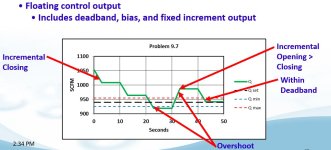
I have had success with some pretty sloppy valve actuators by using bias on my controller output. This was usually done with floating control, but some PID algorithms can bias the output too.

The principle is that the increment of travel in one direction is large than the increment in the other direction. After a few iterations, the backlash is canceled out and you end up with the desired process variable. In one extreme I kept track of the last direction of travel. If I was reversing the direction in my next increment added a little extra travel.

bias.JPG
 

Similar Topics

Hi there, We have a system at a water treatment plant where large raw water tanks feed into the plant that's all on the same level. At high tank...
Replies
18
Views
3,743
Hello! I need to control a sinter moisture in a mixing drum. I have a moisture meter with analog output 4-20 mA connected to analog input of PLC...
Replies
5
Views
4,641
Quick question. I have a PID controller that has the following parameters Process: Flowrate (L/s) Setpoint: FlowrateSP (L/s) Output: ValvePIDOut...
Replies
2
Views
2,461
Hello guys, The processor is a SLC 5/04 using RSlogix 500. Have a question about a proportional valve on our hydraulic system on one of our...
Replies
3
Views
3,608
Hey guys, I am new at this and trying to figure out a way to control the speed of a hydraulic rotary actuator such that it starts slowly ...
Replies
6
Views
6,342
Back
Top Bottom