Wye-Delta Two-Speed Control

keshik

Lifetime Supporting Member
Join Date
Jun 2011
Location
Portland, OR
Posts
408
Hello,

I have a question about wye (star)/delta two speed motor control.

I've attached a picture of the system that I inherited from an Italian company. QMPF-1 is a 32 amp max starter and QMPF-2 is a 63 amp max starter.

My first question is on wiring this system to a 12-lead motor. This is what my best guess is:

411 --> T12
412 --> T10
413 --> T11

415 --> T1
417 --> T2
419 --> T3

inside the enclosure:
T7 --> T4
T8 --> T5
T9 --> T6

Does this look correct?

My next question is in regards to starting this system. This is what I figure:
Energize KM-PF2.1 (shorting contactor)
Energize KM-PF2.2
(wait until second speed is needed)
De-energize KM-PF2.1 (shorting contactor)
Energize KM-PF1

Does that make sense?

My last question is in regards to starter sizing. It seems odd to me to have (at full speed) two starters of different sizes connected to the load. Are we at this point only using the smaller (second) starter to trip out the panel? Is the first (larger) sized larger to provide most capacity during starting?
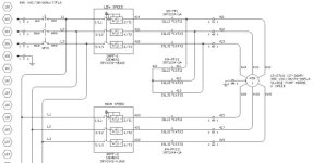
Untitled.jpg
 
Try to post a picture of the other drawing that has the coils to the contactors. And not to argue with Badger but it appears to me to be a standard 2-speed motor starter to me and not a Y Delta starter at all.
 
And not to argue with Badger but it appears to me to be a standard 2-speed motor starter to me and not a Y Delta starter at all.
Yes, there is no indication of the timer that is normally used in a Wye-Delta to switch coils at the preset time.

It appears to be the type of motor (consequent-pole) that has 1st contactor energized for Low Speed, and both contactors energized for High Speed.
 
Last edited:
Probably right. Maybe they have to run in Y (High torque) initially, as it is a sludge pump, nature of the beast could be pretty hard to get going, then go full speed Delta (Low torque) once the medium is moving.
 
The arrangement of the contactors can look like Y-D starter or 2-speed starter.

The connection of the line voltages L1-L2-L3 to the winding pairs U1-U2, V1-V2, W1-W2 tells me that it is a 2-speed starter.
It is not easy to see, but it appears to me that
L1 goes to U1-U2,
L2 goes to V1-V2 and
L3 goes to W1-W2.

If it was a Y-D starter, it would have been
L1 would go to U1-W2,
L2 would go to V1-U2 and
L3 would go to W1-V2.
 
I think this configuration in the attached picture matches the connections in your schematics.

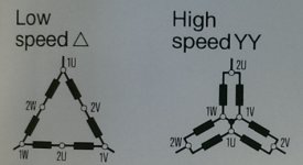
So the "Low speed D" is activated by the contactor KM-PF1.
And the "High speed YY" is activated by the contactors KM-PF2.1 and KM-PF2.2.

edit: Look in the motor terminal box. There is a good chance that a similar diagram is printed on the inside of the lid.

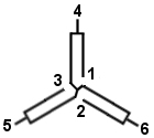
two-speed.jpg
 
The diagram you have shown is for a Dahlander connected , split winding 2 speed motor. Normally these only have 6 terminals. For 12 lead motors , usually the connections are T1 - T12 , T2 - T10 , T3 - T11 , T4 - T7 , T5 - T8 & T6 - T9 . High speed - supply to T1 , T2 , T3 with T4 , T5 & T6 open . Low speed to T4 , T5 , T6 with T1 , T2 & T3 linked together. You have not mentioned either the motor manifacturer or the details from the motor name plate . You must check that the above information is correct for your motor .
The name plate should show the voltage ratings . I suspect you have a 2 speed dual voltage motor which allows star delta starting in both slow and high speeds.
With the diagram shown , the starting inrush current for slow speed is in the order of 150A and double that if starting in high speed from rest . Star / delta starting will reduce this to approx. 60A & 120A .
From your post I infer you are designing your own starter so don't forget to interlock the slow and shunt contactors and prevent the slow and high speeds from being selected together . Usually a change-over switch is used for the latter .

Paul
 
I must apologise , I gave the connections for constant horsepower . The winding connections are as previously mentioned but the connections to your starter are as follows :-
411 - T1 & T12
412 - T2 & T10
413 - T3 & T11
415 - T6 & T9
417 - T4 & T7
419 - T5 & T8
I must also say I'm sorry but I can't find the connections for star/delta starting of a 2 speed motor .
To answer the question about two overloads. At slow speed less power and therefore less current is drawn by the motor so to fully protect it , a smaller rating of overload is used at the slower speed.
Again please check the motor ratings plate and the inside of the connection box lid to verify that I have given you the correct information for your motor .
Paul
 
Thanks for all of the responses. Part of the issue is that the machine is in Alberta and I'm in Oregon. Hard to easily look at things then.

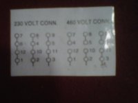
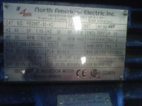
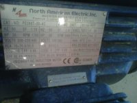
I've attached the picture that the onsite electrical sent me of the wiring diagram inside the motor. I'm trying to get the nameplate from him right now. Does this look more like a standard motor or could it also be a dual speed, single winding motor?

IMG00070-20140909-1511.jpg
 
It's also possible that this is not the original motor that was supposed to go with this machine. One of the joys of being about four levels deep in customers and contractors.
 
Looks like a single speed motor to me. From the connection diagram you gave it does not look like a wye delta motor or a multiple speed motor either. If this machine went two speeds before I don't believe it will do so again until something is changed.

I noticed the motor is inverter rated. Was this machine converted or planned to be converted to vfd control?
 
That sure looks like a two speed motor to me with two separate windings one for each speed. Only one of two possible nameplates was provided, there should be another for the other sets of windings. You will have either 9 (maybe 12) leads for each speed since motor is dual voltage.

Dan Bentler
 
I must apologise , I gave the connections for constant horsepower . The winding connections are as previously mentioned but the connections to your starter are as follows :-
411 - T1 & T12
412 - T2 & T10
413 - T3 & T11
415 - T6 & T9
417 - T4 & T7
419 - T5 & T8
I must also say I'm sorry but I can't find the connections for star/delta starting of a 2 speed motor .
To answer the question about two overloads. At slow speed less power and therefore less current is drawn by the motor so to fully protect it , a smaller rating of overload is used at the slower speed.
Again please check the motor ratings plate and the inside of the connection box lid to verify that I have given you the correct information for your motor .
Paul

Thanks for this Pal; this helped things make sense for me.

After reading a bunch on the subject I think what I'm really looking at is a two speed, single winding motor, that will be running with variable torque (pump application). This is a little more obscure it seems in that most motor diagrams that I've been seeing have been six lead, not twelve.

Looking at this page http://www.joliettech.com/3ph_motors_2_speed_single_winding.htm you can see the connection information for different three phase, two-speed, single winding motors, in both NEMA and IEC nomenclature. Our Italian friends strike again with their IEC wording and make things a bit more confusing for those of us in the western hemisphere. :)
variable_torque_connection.jpg


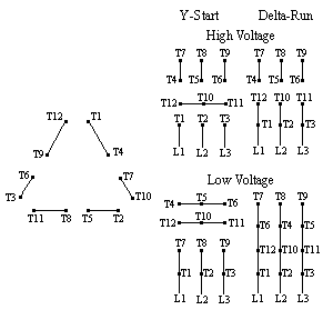
Using Pal's wiring, we basically use the terminal blocks inside the control enclosure to close off the extra six terminal leads and render it down to a six lead motor. This does result in the terminal numbers being moved around a bit. See the below image for the terminal numbers of a twelve lead.
105-2b.gif


Once you continue on with Pal's wiring, you get a Delta configuration in low speed (remember that 4/7, 6/8, 6/9 are joined together by the connections for high speed - they just don't directly see the line voltage at low speed). Once you move to high speed 1/12, 2/10, and 3/11 are all joined together to form a wye center connection. After this occurs, L1 is applied to 6/9, L2 to 4/7, and L3 to 5/8. The result of this is that there is now a two wye connection from each line voltage to the center point. For example, L1 gets to the center point both through the 9/12 winding and the 3/6 winding. I believe that this method of motor connections is called the Dahlander connection.

That raises what is hopefully my final question(s): motor protection and wire sizing. Any recommendations?
 

Similar Topics

Stupid question. I have a motor that is Y-start Delta run, but I plan to start it direct-on-line (motor documentation says this is acceptable)...
Replies
4
Views
1,503
I know people have talked about your incoming power supply as being wye or delta. I don't really understand all that, maybe someone can give us...
Replies
1
Views
1,320
I have a 9 leads motor, I would like to wire it to Wye Start and Delta run connection. Can this be done? Thanks.
Replies
20
Views
3,892
Hello all, This is not my area of expertise, and I would like to hear your comments, not just what the theory says. What are the pros and cons of...
Replies
28
Views
13,258
Scenario is as follows: I have a 460VAC, 60Hz,3 phase, 1750RPM, 500Amp induction motor designed to operate on a 480VAC Wye start/ Delta run...
Replies
8
Views
5,013
Back
Top Bottom