Hopefully this will help you guys out...
roxusa said:
Anyone have a wiring diagram for MSR138DP wired single channel 1 N.C. Automatic reset. I have searched and Rockwell says it can be wired this way but show no print. They only show 2 channel- and a light curtain.
Any help will be appreciated. Thanks
Firstly, to clear up what Allen Bradley are stating you can do, and how you are interpreting it. It is a little bit confusing...
A lot of us refer to the internal, monitored input circuits on a safety relay as "Channels". When Allen Bradley refer to "Single Channel" or "1-CH;N.C.", they are actually referring to the input circuit external to the relay, such as an Emergency Stop contact, not an internal Channel on the Monitoring Safety Relay (MSR). Technically both are Channels, but the internal are more referred to as Logic Channel 1 and 2, the external being just Channel 1 and 2.
So it might easily be assumed that Single Channel (1-CH;N.C.) means you are wiring out and back through 1 safety device Channel to Logic Channel 1 of the safety relay, looping out Logic Channel 2. You are actually still using both Logic Channels on the relay, but via only 1 Channel on the safety device.
It's easy to get your Channels crossed!

If you examine the example wiring diagrams, you only see which terminals are designated for the external safety device Channels. You cannot fully see their relationship to the internal Logic Channels.
You have to refer to the logic diagram of Allen Bradley MSR's to better understand how the external terminals are connected to the internal logic circuits.
Channel 1:
S11 is a +24VDC supply which serves as the source supply for Channel 1. This goes out through the first Channel and back to S12. S12 is the +24VDC return supply to power Logic Channel 1. The -24VDC supply required for Logic Channel 1 is wired internally to the -24VDC supply. So Channel 1 is switching +24VDC between S11 and S12 to power Logic Channel 1.
Channel 2:
How you wire Logic Channel 2 determines whether you are using Single Channel or Dual Channel inputs from the safety device.
Again, if you examine the example Dual Channel wiring diagrams, you will see S21 and S22 are similarly used to connect Channel 2 to Logic Channel 2. However, if you look at the logic diagram, you will see that S21 and S22 switch -24VDC.
The key in all this is terminal S52. S52 is the +24VDC supply for Logic Channel 2 and S22 is the -24VDC supply.
When wiring Dual Channel (2-CH;4 wire) - S11 and S12 switch +24VDC to Logic Channel 1. S21 and S22 switch -24VDC to Logic Channel 2. So S52 is linked to S11 to provide a permanent +24VDC supply on Logic Channel 2.
When wiring Dual Channel (2-CH;3 wire) - S11 supplies both Channel 1 and 2 contacts on the safety device, with 2 separate inputs back to S12 and S52 on the Logic Channels. S21 and S22 are looped out.
When wiring Single Channel (1-CH;N.C.) - Again, S11 and S12 switch +24VDC to Logic Channel 1. You are correct in assuming you link S21 to S22, but this does not loop out Logic Channel 2. It merely supplies one side of it i.e. the -24VDC. The +24VDC for Logic Channel 2 is supplied via S52. So, for a Single Channel input from the safety device, you wire the return wire to both S12 and S52. This circuit allows 1 Channel to make and break both monitored safety relay Logic Channels. This switches +24VDC between S11 and both S12 and S52.
In order to support simultaneous make/break of both Logic Channels, the MSR's "Input simultaneity" must be "infinite".
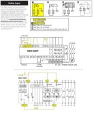
In the attachment, circuit 1 at the top, marked yellow, is AB's official wiring diagram for Single Channel, 1-CH;N.C. You can also see the other wiring options. Circuit 4 is probably the most widely used, but I've seen and wired circuit 2 many times in the past.
The wiring and logic diagrams are below. These are not official. I created them for demonstration purposes. My edits in yellow show how you would wire Single Channel to Dual Logic Channels. The Automatic Reset that you inquired about is also shown.
There are other aspects of this particular relay which I haven't mentioned. If you have any further questions ask away.
G.


