CCW Confusion

dcam

Lifetime Supporting Member
Join Date
Apr 2012
Location
Merced Ca
Posts
161
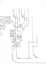
I'm trying to choreograph two inputs from photo eyes to control the timing of a conveyor brake which indexes boxes onto a dynamic weigh scale. Line one running small boxes (shorter brake release time )and line two running big boxes(longer brake release time). Is there a way to do this using one of the many function blocks in CCW? attached is crude drawing of conveyor system in question. I'm trying to choreograph two inputs from photo eyes to control the timing of a conveyor brake which indexes boxes onto a dynamic weigh scale. Line one running small boxes (shorter brake release time )and line two running big boxes(longer brake release time). Is there a way to do this using one of the many function blocks in CCW? attached is crude drawing of conveyor system in question.

scan0001.jpg
 
Is there a way to do this using one of the many function blocks in CCW?
Probably is, if we knew what "CCW" means. However, there are certainly plenty of other ways to do this job with a PLC program.

It appears that you can have many boxes (big and small) between the gates and lined up (with no spaces) before the brake. A Bit-Shift Register could be used to track the Big and Small boxes up to the Brake position. Insert 0 (= Small), or 1 (= Big) into the shift register each time it indexes, and every time the brake releases a box, the Bit-Shift register is triggered to index to the next position, while at the same time, a new box is released at one of the gates. At the brake, if the next bit in the Bit-Shift Register is a 0, then you brake for Small, if a 1, then you brake for Large.
 
Last edited:
Probably is, if we knew what "CCW" means. However, there are certainly plenty of other ways to do this job with a PLC program.

I am ASSuming that he means Connected Components Workbench.

If he clarifies that part, and what PLC etc he is using we can give him some help.

Mark
 
yes im sorry....connected components workbench and i have a micro810 on order .we used to only run big boxes on these lines. now production wants to run small boxes on line 1 and big boxes on line 2.because packing time differs various combinations of big and small boxes will que up at brake to cross scale. there will most likely be no spacing between boxes because the conveyor brake will cause them to bunch up. i need a register that will retain the order of big and small boxes. this register will control the brake release time for each size....
 
In your Rockwell Automation Connected Components Workbench program, under "User Defined Function Blocks, under the Block instrtuction ("Instruction Block Selector"), is there any type of Bit-Shift Register in any of the listings? (It could be under "Data Manipulation").

If not, you will have to "roll your own" Bit-Shift Register, using memory storage locations. Okie (Paul) can help you with that! In other words, you will have to create a memory area that will simulate (virtually track in PLC memory) the physical movement of each box from the gates to the brake. Because these bits will shift when the boxes move, then the arrival of a bit at a certain memory location will signal the arrival of a certain-sized box at the brake.

Because you have only two different sizes of boxes, you can use only 1 Bit-Shift Register to simulate Big and Small boxes, because each bit can be two states, 0 or 1. Just decide which you want to represent each size, and find a memory file type and area where you have enough free bits to represent the physical distance from the gates to the brake. You will need to find out how fast the bits will move, and how many bits will be needed to represent in PLC memory the maximum physical BIG-box positions between the two end points (marked "BOXES ACCUMULATE" on your sketch). This is the maximum number of boxes of any size, that should be allowed on the conveyor between the gates and the brake. That will allow your bit-shift to work correctly. If it turns out that all the boxes are small, then that is okay, as long as there are quantity allowed on the belt than the maximum number of large boxes that will fit in the same space. The reason is that your bit-shift register is going to have a constant number of spaces, between the Entry Point and the Exit point, and you must prevent the number of boxes, in the same physical space, from ever being more than that number.

Your simulated Shift Register should be triggered each time a box leaves the brake. At the same time, a new box is fed in at one of the two gates, and a 1 or 0 bit is inserted into memory to represent the box size. At the brake, as a known box size arrives (based on the bit being shifted to that position), the correct brake time is triggered, and the box is passed, which triggers the next gate release and also the 1-or-0 bit insertion, and then a bit shift that moves each bit 1 position toward the Exit Bit (Brake Position).
 
Last edited:
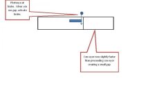
If I was designing this, I would try to create a gap between the 2 different conveyors (using a faster speed). Then install a photoeye at the brake. When the photoeye sees a gap and then a box, activate the brake. It won't matter what size the boxes are then.

untitled.jpg
 

Attachments

  • Document1.pdf
    15.9 KB · Views: 25
Big Box / Small Box / no box; If you use '1' for a big box and '0' for a small box, are you sure there will never be a 'no box' condition ? Does it matter if there is a 'phantom' small box assigned to a space on the conveyor ?
 
If I was designing this, I would try to create a gap between the 2 different conveyors (using a faster speed). Then install a photoeye at the brake. When the photoeye sees a gap and then a box, activate the brake. It won't matter what size the boxes are then.
Bruce,
Maybe you are right, but he said that there are no gaps possible.
there will most likely be no spacing between boxes because the conveyor brake will cause them to bunch up.
Zooming in on the posted sketch, the brake release must be on longer to move big boxes onto the next scale section. The only way I see to know how long to release the brake (with no gaps) is to for the PLC to know the sequence of big/small boxes. However, when the box sizes change, the program will have to be modified, so this may not be very practical long-term. It may be that a method can be set up to input the big-box length, and the PLC can then divide the total distance by the big-box length, and adjust the length of the bit-shift register to that number. The brake time will need to be scaled to the box length also.

Glenn,
If the Bit-Shift register is only filled with a 0 or 1 when a big or small box is released onto the conveyor, then there will be no empty slots in the shift register (although there may be empty space on the conveyor between the gates and the brake if some or all of the boxes are small). That is why I said the number of big boxes that will fit must be known, and the shift register must not contain more spaces than that. Otherwise it will not work very well without additional equipment, such as a spacing conveyor to add spaces at this point! Also, when the conveyor space fills with big boxes, there must be a flag that prevents releasing any more until a space is available. In fact, to load the space fully, the PLC will have to know how many of each type, and how many of all mixtures can fit. It would be necessary to keep a running total of the lengths of the boxes to determine when no more will fit. That is why I would figure the number of big boxes, and then only allow that Quantity of boxes to be released onto the conveyor, even if some are small and there is still space available.
 
Last edited:
Just brainstorming here, and this "storm" may be no more than a mere zephyr. I'm not sure if it's feasible at all in CCW since I've only tinkered around with a single, very simple application.

The brake disengages for a time to release a box to the next step, then re-engages. The disengage time varies according to box size (bigger boxes take longer to release). Is the engagement time constant, or is there an external trigger to release the next box? Maybe "weighing done"? Doesn't really matter, I guess.

Instead of using a bit shift, can we instead use a FIFO integer array? Each element in the array would be a number representing either what kind of box it is, or the timer preset directly (one possible advantage is that you could maybe run more than 2 box sizes with little difficulty). You would have to keep track of the end of the array (where the boxes are added at the end of the line) with a number that you would increment every time you added a box and decremented every time a box was released. The array would need to be at least big enough to handle a conveyor full of the smallest box to be run.
 
Thinking more about using a Bit-Shift operation, I think now that the gates should control the Bit-Shift trigger (inserting new bit and indexing Output to next bit). I think an additional photoswitch will be needed at the brake to not allow a bit-shift unless the next box has made it to the brake position. That way, the conveyor can fill without releasing a box every time a new one is inserted. When the conveyor has the maximum number of big boxes, then the gates should be inhibited from releasing any more until a space opens (the scale is empty and can accept the next box).

The array would need to be at least big enough to handle a conveyor full of the smallest box to be run.
I thought that too, at first. But look what happens if all the boxes happen to be big (maybe the big size is all that is being run that day). Say the space can hold 10 big boxes, but your shift register (be it a FIFO or a Bit-Shift) has 15 spaces for 15 small boxes. Now your shift register has 5 empty spaces with no corresponding box, even though the conveyor space is full. Unlesss there is logic to prevent more than the maximum of 10 big boxes, you could be releasing 5 big boxes with no space to put them in. This problem could be handled in the PLC program if the length of each box is known to the PLC.

There is a note on the sketch that reads:
"These P.E.'s and gates are used by system for label order".
This means that somewhere there already is a queue that contains the order of big and small boxes on the conveyor. If that part of the existing system PLC program is available, then the same list can be used to also control the brake timing.
 
Last edited:

Similar Topics

Hello. Has anyone ran into an issue with HSC on 2080-LC20. It run a cut off press and every so often after resetting to 0 it does not count...
Replies
0
Views
52
I am running CCW 13 trying to upload to a micro 820 vers.12 I get an output message OPC server is unable to load project controller. Please help!
Replies
5
Views
169
How to retain Values in CCW software? I am using CCW software and I can not find the Retain function in this software. Not even local or global...
Replies
2
Views
158
I am new In a CCW and as a beginner I am trying to learn programming but i am noticing that my CCW software is taking around 1 minute to download...
Replies
2
Views
97
Back
Top Bottom