Tough Nut...

Rick,

I believe the level sensor will provide an analog reading that will allow Terry to trak the rate of rise/fall and limits. According to Terry's 1'st post the center petcock is at the desired level. So any reading above or below the center petcock would require some action to fill or drain. In reality Terry would have slightly less of a differential then the petcocks would show with a sightglass but maybe he can live with that??

Anyway my thought was to make as few alterations to the origional equipment as possable, simplifying the installiation, and allowing Terry to go back to square one if it dos'nt work out.
 
I am going to assume that the air pressure in the accumulator system can vary independently from the water level. Therefore, for a pressure sensing system to work for level indication, it has to be the difference between the very top of the chamber and the very bottol of the chamber. If Mike spreads his tap points out, changes his level sensor to a differerntial pressure sensor, his system will work. In fact, since air pressure is going to be essentially uniform throughout all tanks, he can tap the low side of his differential pressure sensor to any physical high point on the air side.

If you can't find a differential pressure sensor with the right characteristics, you could use two absolute pressure transmitters and subtract in the PLC.
 
Last edited:
Tom,

I dont understand your last post. With that particular sensor, (originally suggested by JesperMP) I dont think it responds to pressure, but is able to withstand the tank pressure. I dont think that the take pressure otherwise effects the 11500 sensor. So whatever the pressure, it will transmit the level.

BTW this is a continuous level sensor. So irregardless of tank pressure, Terry can use it to follow the level between the two petcocks.

Regards, Mike
 
Last edited:
You're right, Mike. That system will accurately track the level between the two petcock taps. However, as I understand Terry's original objective, he wants to track level above and below the two taps. That is why I didn't think your system would meet all of his criteria.
 
Tom,

Doing a quick re-re-reading of the origional post, I guess you right. The 11500 z level sensor can come with probes from 2 meters to 100 mm in length. So if he wants a wider reading the sensing chamber will have to be longer and tap into the top and bottom of the system, like you said.

However Terry does it, I vote for this particular level sensor. Besides all the other suggestions (attornys, ex-wifes, fish, and canarys) require very hi maintenance....
 
I believe that the E+H sensor can come with rods that are longer than 2 meters. It just has to be ordered specially. Our company uses rods that has a bend (!), so "everything" that the customer asks goes.

I would also consider a DP sensor, if existing taps can be used.

I think that the final solution will depend on how it can be fitted to the existing installation with as little changes to the piping system as possible.

edit: the "sensing chamber" is not a bad idea. It will be simpler to have such a thing manufactured than to make any changes to the existing vessel.
 
Last edited:
About using a differential pressure transmitter:

It would have to be a high precission type.

If for example the Rosemount 1151 was used, it has an accuracy of 0.1% at a max turndown of 1 to 10 (below that the accuracy decreases). With a rated pressure of 6000 PSI, and a calibrated range of 600 PSI it would have an accuracy of 600 Psi x 0.1/100 = 0.6 PSI = 40 cm water column.
edit: I just notice that the model 1151HP (hi pressure ?) has an "overpressure limit" of "4500 psia" while a 1151 with the ordering code "0" has an "upper range limit" of "6000 psi". Not sure if that means if the maximum is 4500 or 6000 psi.
Also not sure if this applies to the absolute or the differntial pressure. The "psia" seems to indicate absolute pressure, but that doesnt make any sense to me.

If that is not acceptable, a Rosemount 3051S can be used in stead which has an accuracy of 0.04% and a max turn down of 200 to 1. That would make the accuracy 30 Psi x 0.04/100 = 0.012 PSI = 0.8 cm water column.

edit again: The model 3051S_CD must be ordered with the option code "P0" to withstand 6092 PSI.
 
Last edited:
INSTEAD OF JUST USING YOUR LEVEL PROBES AS IDICATORS USE THEM AS FILL OR DUMP SIGNALS AS WELL.
Terry Woods said:
Well... let's see what you can come up with...

We have a hydraulic press. The hydraulic pressures contained in two accumulator systems close the press. The first accumulator provides low pressure (approx 500-psi) and the second accumulator provides high pressure (approx 5000-psi, approx 150F). The low-pressure accumulator provides approximately 95% of the closing. The high-pressure accumulator provides the last 5% of closing.

It is, of course, very important that the accumulators have the correct amount of water (water mixed with oil) when the accumulators charge to their "set-point pressure". This is easily determined in the low-pressure system by means of a set of float-switches.

Last week, we had a severe air leak. (Apparently, a smaller leak had been there for quite a while.) It was a few hours before the night crew identified the problem and got it isolated. In the meantime, all five bottles filled with water.

When they completed the repairs, they tried a cycle. When the high-pressure phase of the cycle began, the pressure dropped from 4500 psi to 1200 psi... in about... one second. A normal 30-second close took about 5-minutes. A normal cycle-time is five-minutes.

So... here is my problem. I need to be able to monitor the water level in the high-pressure system. At this time, the only means we have to judge the water level is by means of a set of three petcocks mounted on a tube. The tube is mounted in parallel with the airside and the waterside of the high-pressure accumulator. Of the three petcocks, the center petcock is at the required level. The other petcocks are mounted 2-inches above and below the center petcock. It is easy to determine the level of the water as long as the water is where it should be (+/- 2").

Here is a diagram of the High Pressure Accumulator System.

4123f8764b65346e.jpg


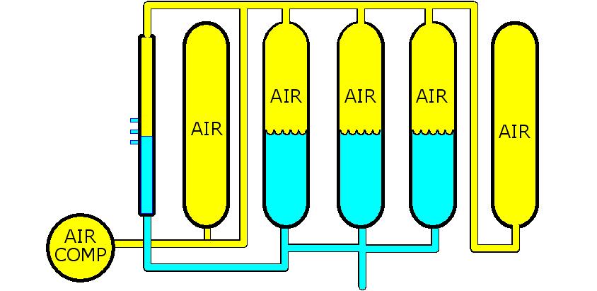
The problem is that once the water level moves out of that range it is impossible to know the trend. Once it is determined that the level is not where it should be, actions are taken to try to restore the water to the proper level (either add air or add water). Adding water is the easier task. Adding air, on the other hand, is a long process. While adding air, however, we do not know if we are gaining ground or losing ground. That is, once the water level is above the top petcock, it is impossible to know, on a cycle to cycle basis, whether the "at pressure" water level is increasing or decreasing.

The same issue (to a lesser degree) applies when the water level is below the bottom pet-****.

I would really like to use a 4-20mA sensor to provide continuous level information.
beerchug
 
Hokay...

As Jesper said, my vessel is certified (and 3" thick). I'm not about to violate the vessel integrity.

I have tried to use a Differential Pressure Sensor in the past. It was, is, ...was a Foxboro unit. It's dead now. It died on the first cycle.

I had it mounted in a manner similar to what Mike suggested, except I made the connections at the extreme upper and lower points so I could take advantage of the entire fluid/air height.

When I opened the lines to the sensor, the sensor gave a reasonable reading. Then we started a cycle. As fluid left the bottles, the reading followed reasonably. Shortly after discharging, it was time to recharge the accumulator (the rest of the process carries on in the meantime).

So... two 100HP pumps (4-pistons each) begin to recharge the accumulator. We watched as the reading slowly returned toward the normal level. All was progressing well. At that point, the pressure in the accumulator was something around 2500 psi. However, very soon, the level reading started to become somewhat erratic. We could see that it was becoming more erratic by the moment.

And then... the transmitter display went to sleep... as in when Uncle Louie says "Dat bum is sleepin' wid da fishies" (did I mention the lovely concrete-boots that Uncle Louie gave to the bum before said bum went to visit the fishies?").

So... the transmitter died.

At the time, the system was subject to some rather extreme hydraulic hammering. The hammering effect has produced interesting results in various parts of the system. There have been more than a few times, when coming to work, I wondered, how is it that I find myself at "The Bellagio" (the dancing-waters, don't cha know?). Sometimes, just like at The Bellagio, the only thing you want to do is sit there and stare in awe. Marvelous, simply marvelous!

I've since taken measures to minimize the hammering. I miss those water shows... they were really, cool!

After a few phone calls, it was ascertained that the sensor failed because of the hammering. The sensor was rated well above our maximum pressure but it could not take the dp/dt (hammering). The suggested solution was to install "snubbers" to dampen the hammer effect. That sounded reasonable until I became aware that "snubbers" have a "life", and when they fail, they fail immediately. That would mean... another transmitter sleepin' wi da fishies!

So, we decided not to go that route; we had to find a better way. That was a couple of years ago. I find it very hard to remember to feed the chickens when I am being chased by a bull... don't you? So, many bulls later... and having recently experienced water coming out of the "air pressure safety valve" in the accumulator system, it is now time to face this bull once again (sorry again, chickens).

The ultimate cause of this pursuit is that the integrity of the airside of the accumulator system is always suspect. We have so much noise in the area that you couldn't hear a leak if it had teeth and bit you in the a$$. All it takes to lose the expected water level is for a small leak to develop.

Now, someone suggested monitoring the amount of water removed from a storage tank and pumped into the accumulator. That could work... if the system wasn't inherently leaky and if there were not two systems (high pressure and low pressure) drawing from that storage tank.

The "technical" answer to management is... the system is too "dynamic" in it's distribution balance. The "straight" answer is... the system is a sieve! The most reliable part of the system is the airside of the accumulator; and it cannot be trusted.

I can handle all of the leaks on the waterside. I need to find a way to monitor the leaks on the airside so that I can handle the leaks on the airside. The only clearly indicative clue is the level of the water when the water and air is at pressure. As I lose air, the water level rises before it comes to pressure.

If I lose air, I can apply a remedy (5000 psi air compressor) but I need to know if I'm winning or losing on a cycle to cycle basis.

So... I'm accepting the following:
  • Murphy lives.
  • Murphy is registered to vote.
  • Murphy's voter's registration card shows my place of employment as his home address.
I'm also accepting the concept of atrophy as a universal constant (damn, that ain't the right word... you know what I mean... the one where all things tend to go to pi$$... hmm, I think I need another MGD).

Fill & Dump is pressure and process controlled; this is not an issue.

I need to know the TREND from cycle to cycle. I need to know what the real water level is from cycle to cycle WHILE corrective actions are being taken.

I do not want to use any kind of fixed position level sensors. They are no better than those damned idiot lights in your car that tell you... "Uh... excuse me... you ran out of oil about 10 miles back... just thought you might like to know."

So far, I expect that I will build another tube in parallel with my petcock tube. The old, reliable, although, not very informative, petcocks will always work.

I'm looking to insert a sensor into this second tube. I'm looking at the one from K-TEL (LU2E) and the one Jesper mentioned. My bottles are about 12-feet tall so I'll need a pretty long probe. Actually, I'm only worried about the upper 6-8 feet.

I'll keep you posted.
 
Terry,

can you tap into one of the air lines going from the compressor to the top of the tanks? If so you can place the "sensing chamber" or paralell tube that would house the 11500 Z sensor between the bottom petcock and the top of the tanks.
 
Terry Woods said:
I can handle all of the leaks on the waterside. I need to find a way to monitor the leaks on the airside so that I can handle the leaks on the airside. The only clearly indicative clue is the level of the water when the water and air is at pressure. As I lose air, the water level rises before it comes to pressure.

Might it be possible to simply monitor air pressure throughout the cycle? Have your program 'learn' the pressure changes present during a 'normal' cycle, and alarm when pressures fall outside the limits. IOW, whether timed, or triggered by events in the process, you could check the measured pressure at specific points throughout the process and compare them to 'known good' values.

In any case, it might be helpful to at least graph the pressure changes during a non-leaking cycle and compare it to what a graph of a leaking cycle looks like. You might discover an easy way to determine when a leak is occurring... :confused:

BE the accumulator!... :D

beerchug

-Eric
 

Similar Topics

Good Morning, I have a customer who would potentially like to install tail roll sensors on their conveyors in their quarries. The plc will monitor...
Replies
14
Views
4,140
Hi, I'm wondering how to program a function that has an integer(or word) input but return the value contains in the address of the input. for...
Replies
8
Views
4,013
Someone had posted a touch screen here a couple weeks back that looked to be real tough. It even took a shotgun blast. I can't seem to find that...
Replies
1
Views
1,567
Not sure why I'm having a tough time but all my logic seems to be right but its not working. I'm trying to get the LEN function to get a value...
Replies
0
Views
1,496
Dear guys, the FIFO is a pain for me. I am using siemens s7 to program it. When I use FC84 ATT table to store the data, it can work properly. But...
Replies
7
Views
4,486
Back
Top Bottom