Identify Slot in PLC 5

cstep7263

Member
Join Date
Dec 2019
Location
Katy, TX
Posts
35
Hello,
I'm trying to identify which Field devices is wired into which PLC Slot in the chassis. I am not familiar with PLC 5. I open the Code and I see addresses for Discrete inputs and Outputs are on the same slot: I:004/0 O:004/0. How do I know what slot these addresses are on by looking at the Input Output Data File? How do I find out if it's Half Slot or 1 Slot or 2 Slot by looking at the Data File?
 
The PLC-5 inherited its slot and rack addressing system from the PLC-2 in the late 1970's and it is... "arcane" is a generous word. There are complementary racks and and half/full/double modes and lots of other stuff.

You can generally figure out how a system is configured by looking at the physical racks, and at the configuration of the RIO scanner channel in RSLogix 5, and sometimes using specific known inputs and outputs as guideposts.

For Rack 00, which is the chassis the processor is installed in, you might have to do a little more inferring. In particular the "1/2 slot, 1 slot, 2 slot" mode is set by DIP switches you can't see without shutting down.

My *guess* is that you're in 2-slot addressing mode, where Inputs and Outputs share the same memory address "group" number when installed next to one another.

Physically, you're probably looking at a 16-slot chassis, from left-to-right:

Rack 00 Group 0 (I:000)
Rack 00 Group 0 (O:000)
Rack 00 Group 1 (I:001)
Rack 00 Group 1 (O:001)
Rack 00 Group 2 (I:002)
Rack 00 Group 2 (O:002)
Rack 00 Group 3 (I:003)
Rack 00 Group 3 (O:003)
Rack 00 Group 4 (I:004)
Rack 00 Group 4 (O:004)

Rack 00 Group 5 (I:005)
Rack 00 Group 5 (O:005)
Rack 00 Group 6 (I:006)
Rack 00 Group 6 (O:006)
Rack 00 Group 7 (I:007)
Rack 00 Group 7 (O:007)
 
So do the Group number represent a Slot on the chassis?

Not directly. That is where the addressing mode comes in. In two-slot addressing each two slots is one I/O Group. So after the CPU, count 0, 0, 1, 1, 2, 2...etc

To dig deeper, can you tell us some details on the modules in that chassis? Are the indicators little red lights or are they numbers that light up? Tell us what modules you see in each slot. If you can't identify the part number, then just a short description.

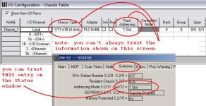
If you can get online with the controller, open the S2 Status Data file. Click on the Switches tab and look for the Addressing Mode. Is that 1-slot, 2-slot, or 1/2-slot?

OG
 
I actually have IO addresses in all of the Below and I don't see a Group 6.

I:003/1
I:003/2
I:003/3
I:003/4
I:003/5
I:003/6
I:003/7
I:003/10
I:003/11
I:003/12
I:003/13
I:003/14
I:003/15
I:003/17

I:004/0
I:004/1
I:004/2
I:004/3
I:004/4
I:004/5
I:004/6
I:004/7
I:004/10
I:004/11
I:004/12
I:004/13
I:004/14
I:004/15
I:004/16
I:004/17

O:004/1
O:004/2
O:004/3
O:004/4
O:004/5
O:004/6
O:004/7
O:004/10
O:004/11
O:004/12
O:004/13
O:004/14
O:004/15
O:004/16
O:004/17
 
And... be thorough. Be careful. Verify what you're looking at. Take notes.

I have a special nightmare about a system where the main gas valve and the exhaust purge fan were on Output 0 of the module in Group 0 on different I/O racks. After a major maintenance shutdown, a novice installed the network adapters in the wrong places.

Long story short, kaboom.

Any time you're working on a system or platform you are not familiar with, be extra careful.

Also: thanks OG, I forgot there was a switches status indication in the S:2 file for the PLC-5, so you don't have to take the CPU out of the chassis.
 
I'm looking at the Program Offline. The PLC is in another state and I'm unable to look at the Chassis physically. One moment I'm trying to get online.
 
If you can get online with the controller, open the S2 Status Data file. Click on the Switches tab and look for the Addressing Mode. Is that 1-slot, 2-slot, or 1/2-slot?

OG[/QUOTE]

It shows 1 Slot. So every Card in the Chassis is 1 Slot?
 
from post #1 ...

I open the Code and I see addresses for Discrete inputs and Outputs are on the same slot: I:004/0 O:004/0.

from post #9 ...

It shows 1 Slot. So every Card in the Chassis is 1 Slot?

CAUTION: without knowing more about your system, these two statements seem to be contradictory ...

can you have someone in the field take a snapshot and post it here as an attachment? ...
 
1 and 2 slot addressing
There is a dip switch in back of the chassis
I would have to look at the manual but I it this way to refresh my memory
If you look at the front of the chassis the slots are arranged in groups of 2 slots
In 1 slot addressing the 2 slots in the group have the same address example 4
As 14 slot chassis would be one slot addresses group 0-7 with 2 modules per group
With that you can have each group can have 1 input and one output both will have the same slot address you can also have 2 8 point modules in each slot input or output
The left slot would be the low order bits (0-7) and the right slot would be high order bits (8-15)
In the data table both inputs s and outputs are reserved 000 -077 are outputs 100-177 are inputs
The number system is in HEX
011 would be Output group 1 slot 1 ext.
One note if you are not using the reserved I/O table words they can be used else ware in you program just like any other data table words I have had to do that a few time when I ran out of memory
It’s not unusual to see racks with empty slots depending on how the rack is setup if you have more inputs then outputs the right hand slot can only be used for an output so it will be empty
 
once you know for sure what addressing scheme you have - then the figures attached should help ...

NOTICE - when using the RSLogix-5 software to determine the addressing mode, make SURE that you are getting the information from the "Switches" tab on the Processor's Status file ... specifically, do NOT trust any information from the I/O Configuration feature ... that information is set for 1-slot by default and it does NOT get updated unless a programmer manually changes the setting ...

EDIT: I've added another post below - which shows the difference between the two features I'm talking about ...

note also that the Switches tab information refers ONLY to the LOCAL chassis - specifically, the chassis which has the processor located in it ... based on what you've posted so far, this should be the chassis that you're interested in ... BUT ... if you're working with a remote chassis (no processor installed in it) then we need to talk further ...
.
 
Last edited:
It shows 1 Slot. So every Card in the Chassis is 1 Slot?

If it shows 1 Slot addressing in the S2 file it means that the slot addressing that the processor is installed in, is set for 1 slot addressing. There could be remote I/O in another chassis that is set for a different addressing scheme.

If it is set for 1 slot addressing and it is an input module in the 5th slot which would be inputs I:04/00 - I:04/17. I have seen people use O:04/00 - O:04/17 as internal flags, or parts of a program left over from when the chassis was configured for 2 slot addressing.
 

Similar Topics

I received an email from a student with the following code attached. This is supposed to control a floodgate system, and supposed to be written...
Replies
23
Views
777
Hey All. I am working on my home automation system (again). I want to tinker around with my irrigation system. The system itself is pretty...
Replies
9
Views
1,803
I have a CompactLogix 5280 a I am trying to figure out which of the Ethernet ports are A and B. Not finding it in the manual and this is a new...
Replies
2
Views
1,190
I have a project I am designing a quote for an upgrade on. Per the schematic, the PLC I saw and an upload I took, it is run by an AB MicroLogic...
Replies
6
Views
2,677
I have a Versapro project file for a Versamax PLC. Need to identify what type of variables are suitable and made available for BMS system to...
Replies
3
Views
1,705
Back
Top Bottom