Scaling temp. data in C-More Line Trend Graph

Dan_S

Member
Join Date
Jun 2020
Location
Oconomowoc
Posts
7
I'm having an scaling issue using an F0-04THM module card with a Directsoft D0-05DR PLC. My issue is this; the temp data in the PLC has one implied decimal point. A normal numeric indicator can accommodate this, but the line trend graph in the C-More EA9 cannot. My two indicators show the temps, and they are accurate and within .3° from each other at ambient, and respond properly when hit with a heat gun. The graph data, however, is off by a factor of ten, so it's displaying 740° at ambient.
How can I use the logic provided by the F0-04THM and divide that by 10 without affecting the output I have at V2000? I would like to see the numeric display match the chart values, and I don't care to divide every cell in a huge data log by 10 to get to the correct value.
Also, I am using channels 1 and 4, and have the +/- of 2 and 3 jumpered, as well as all the commons.
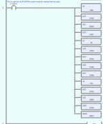
I attached what AD gives as the logic for reading the temp card.
"It's surety I crave, and have none."
Thanks for any assistance.
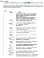
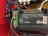
F0–04THM Logic.JPG IMG_1957.jpg
 
Welcome to C-More charting :/


The easiest thing to do is to set up a second Vmemory (say V2010) location that is simply V2000 divided by 10. Have your indicators point at V2000 like you do right now, but point your chart at V2010. You will lose your decimal precision, but that's often not important for charting. If you need to retain it, maybe convert to Real as well. I believe the chart supports real numbers, can't remember if the 05s do or not.
 
But how do I change where the chart is looking?
The only thing I can think of is the "octal statement" in the code.
Just change that to O2010,then add to that ibox column...
LDD V2010
DIV K10
OUTD V2000?
I assume I would have to out to each channel. Can I just
OUTD V2006 (for channel 4)?
Thanks for the help BTW
 
You would need to add another tag to the C-More database, one that is pointing to V2010 (label it temperature-integer, or something). Then configure the chart to use that tag for the temperature pen instead of the tag that is looking at V2000.


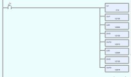
For the PLC code, you would do something like:
LD K10 <Setting up the divide by value
OUT V2100 <Doesn't matter what address this is, example only

LDD V2000 <loads the decimal temperature value
DIVD V2100 <Divides by value in V2100, that we preloaded earlier
OUTD V2010 <Puts the result in V2010


Because you are using double words, you need to use the double divide instruction (unless your readings will never get over 999.9). The double divide instruction doesn't accept a constant (K10), so we need to stash that number in a Vmem location prior to the actual math operation.
 
I tried the suggestions with no success. I placed numeric displays on the front screen and they stayed grayed out. The chart shows only one data line up in the 740 range(still off by x10), and for reasons I don't know it's showing channel 2. I see that the "LDA O2000 loads to 8 registers, but does the "LDD V2000" grab all of those?
Attached modified logic

Pack_A LLogic.JPG
 
Last edited:
First, to answer your question, no the LDD does not grab all 8. LDD is LoadDouble (two Vmem registers), and loads V2000/V2001 (the first temperature channel data). To convert all 4 temperature readings, you will need to duplicate the logic 3 more times (the LD k10, OUT V2100 doesn't need to be duplicated). You need to add LDD V2002, DIVD V2100, OUTD V2012, and so on.


Second, the logic you are using to divide the temp reading by ten needs to be executed on a regular basis. Right now, you have it attached to the module setup rung, which is only triggered once, when the program goes to run mode (SP0 bit is only true for the first scan). You need to separate the divide logic into it's own rung. You can use the every scan bit (SP1) to have the divide operations happen on every scan through the program.


Make those changes and then see if V2010 has the expected readings when viewing the PLC program online (and V2012, etc. after you add the logic for those). After that, we can work on the HMI side.
 
Okay I've made those changes. Real-time values at V2000, 2006 still look good, but the 2010 and 2016 still out. (I'm only using channels 1 and 4)
I moved the SP_0 ladder to the top, the SP_1 to the bottom.

SP_1.JPG SP_2.JPG
 
Just to confirm, you've written the changes to the PLC, and the PLC is in run mode, correct? What do you have in V2000? V2010?
 
Success !!!
I broke up the second divide into a second SP1 rung and it's working great!!!
Thank You for the assistance on this. Never worked with iboxes before.
Kudos given.
 
Great! Glad it's working for you! BTW, none of those are what would be called iboxes. Those are just commands for working with data words.


Iboxes are kind of like macros that use those commands behind the scenes to do the same thing.
 

Similar Topics

I know nothing about simaticnet OPC server. I do know Kepware. I would only ever scale raw to engineering in the PLC, but it is possible to scale...
Replies
5
Views
209
Hi all. I'm working on a rehab and I'm trying to figure stuff out. See screenshot at the bottom. Local:5:I.Data[6] in BTD instruction is a...
Replies
6
Views
697
Hello all, First post here. Hitting a wall with finding info on this topic online, and none of my coworkers have a clue. I have a PanelView...
Replies
10
Views
1,335
Hello, We monitor the temperature of a pipe via a 4-20mA temperature transducer. This goes into DB135(Read Analog Inputs). The issue I have is the...
Replies
0
Views
623
5069 IF8 with a 4-20ma 0-100psi, sealed fixed, no calibration, transducer attached. IF8 is scaled 4ma= 0 psi, 20ma=100psi. If over time the...
Replies
12
Views
2,580
Back
Top Bottom