Slide gate solenoid logic gate logic for RSLogix5000

snehavikas14

Member
Join Date
Jun 2019
Location
hartford
Posts
17
I have to make a slide gate solenoid logic.

below are the requirements and circuit

This example drawing has an E-Loop switch. The tubes with this E-Loop are 9 thru 11 and 13 thru 16.

The gate hand switches are indicated as SW3 in the schematic. Subcontrator to remove the existing wiring of SW3 and replace it with NO contacts from the new relays that are located within the I/O panels. SW3 will then be wired as discrete inputs into the respective I/O panels, please refer to the Panel drawings attached for specific tube/IO panel correlation. For tubes with E-Loops, there will be a separate E-Loop switch that will follow the same suit. The E-Loop switch shall be removed from the existing circuit and replaced by new relays located in the I/O panels. The switch shall then be wired to the I/O panels as digital inputs. The relays for both SW3 and E-Loops are controlled by the PLC, which is triggered from the inputs from the switch inputs
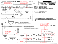
Capture1.PNG
 
i have slide gate selector switch front and selector switch back.....depending upon which one is selected proper slide gate front or back needs to be actuated......i need to implement Eloop logic in that and i have no idea how to do that
 
try to break down what the requirements are into different parts.
get a 11x17 paper and draw out what the items say with the new changes.
you will need the I/o pages referenced in the picture.

1. The gate hand switches are indicated as SW3 in the schematic.
2. Subcontrator to remove the existing wiring of SW3 and replace it with NO contacts from the new relays that are located within the I/O panels.
3. SW3 will then be wired as discrete inputs into the respective I/O panels, please refer to the Panel drawings attached for specific tube/IO panel correlation.
4. For tubes with E-Loops, there will be a separate E-Loop switch that will follow the same suit. The E-Loop switch shall be removed from the existing circuit and replaced by new relays located in the I/O panels.
5. The switch shall then be wired to the I/O panels as digital inputs.
6. The relays for both SW3 and E-Loops are controlled by the PLC, which is triggered from the inputs from the switch inputs

understand each item, post your work, and we will help by offering ideas and suggestions.


james
 
attached is what i worked and as per my understanding...i m pretty new to PLC and dont have experience on reading electrical circuits.

pls respond asap
 
I can't see the last few images you posted for some reason but the ladder logic is pretty much laid out for you in your first image.
Try and follow that. Use the emulator if you are new to plc programming to test your logic in a virtual setting before you break stuff in the real world.
You should really have some experience in circuitry of some kind, from a wiring or engineering point of view before you attempt to write a program with
a hard and fast deadline. Not trying to be rude, but you might consider paying a programming contractor on this one and learning circuitry and programming
on less time sensitive projects. No joke you can really do some damage.
 
Last edited:
jshbnd,


I'm assuming if the OP hired a programmer, the teacher of the class this is for would be upset or maybe not. Just my assumption is all.
 
ohhhhh.... it's for a class.
I feel pretty shtoopid right about now.
I would say that the class is working kind of backwards right now, however.
One should be taught control wiring and ladder diagrams before they drop you in the middle of a programming problem, right?
 
thanks for reply guys...somehow i am unable to post the ladder logic diagram which i made.....let me try again.


Its project is not for a class though
 

Similar Topics

I am fairly new to using WinCC and Siemens Comfort Panels but have experience with other brands. I am trying to animate an image position with a...
Replies
2
Views
980
Crimson 3.0 build 579.003, programming a G308A210. I have a display page set up as a master slide. I have the usual alarm banner across the...
Replies
23
Views
5,626
I looking for a linear slide with position feedback. the slide must be at least 3ft long and cary around 1 pound. A penumatic driven unit is in...
Replies
5
Views
3,090
If an RSView32 works project (version 7.5) consists of several screens, named for example: Screen1 Screen2 Screen3 . . . . Screen-N What is...
Replies
1
Views
1,476
attached a pdf file that i hope makes sense. Looking at some type of linear assembly that would have a 220v type small motor attached to the end...
Replies
11
Views
5,552
Back
Top Bottom