Intermitent ModBus losing communication to drives

remullis

Member
Join Date
Oct 2012
Location
Georgia
Posts
179
I am helping troubleshoot a plant with Modbus communication. We pretty much went through as many connections as we could with limited drawings. At one time today we sustained good comms through the loop for about 20 minutes. I am suspecting loose connections but I am looking for some input or things to look for in this system. The drives are square D and Yoskowa. Typically we lose the drives within seconds or minutes of each other.

Thanks
Rm

The solution to finding the error is to hook up PC to the communication and log everything.

Is it ethernet or serial (RS232/422/485)?
 
2 conductor shield with gnd. Thanks

That's RS-485 then.

Hooking up a PC to log means connecting a computer to the communication and with serial logging software saving every byte that is transmitted and received over the bus for later analysis.

If you have errors in the communication that means that the transmission is re-sent. that should be visible on the messages sent.

You need to figure out what is stopping the transmission. Is it errors on the communicating bus? Often a sender might only retry a certain number of times and then abort communication. This is my guess.

Given that it is an RS-485 bus you need to look if you have fail-safe bias resistors. Is it needed in your case? It depends on the units used. It is the most common RS485 problem. I've made previous posts on it. You need to research this.
 
These are all vfd's on the system. It does have end tap resistors, but by the drawing I should have 120 ohms and I measured 115. If I measured this right.
 
I've had problems before where original installer had used 130-OHM instead of 110-OHM terminating resistors. Worked fine for years but after I added a Drive it had random errors and comm losses.

To make a short story long visually make sure you have the right size resistors at either end.
 
Hopefully I can use the thread for question regarding termination resistors :)

I have only one Modbus RTU slave (Nemo 96HD multifunction power monitor - http://www.imeitaly.com/eng/nemo_hdle.asp). Modbus RTU communication module manual - http://www.rayleigh.com/media/uploads/10781663.pdf.

PLC (serial interface RS-485) acts as a master.

Current setup is:

- no termination resistors,
- cable length < 2 m,
- baudrate: 9.600 Baud,
- data frame: 8 data bits, no parity bit, 1 stop bit.

OK, so everything works fine except that after approximately one, one and a half day I get one error in communication and after that the next reading is already OK. That is generally not a problem as data from power monitor is used only for diagnostic and not control purposes.

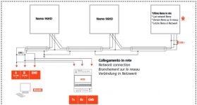
In 2 days, we will revisit the location because we have some other work to do, but I plan to install termination resistors. The thing that bothers me is what resistors to use? As you can see on the picture that I have attached, power meter communication module guide suggests that 220 ohm resistors should be used at both ends, while PLC serial interface guide states: "The serial RS422 and RS485 communication technologies operate with voltage levels on a 2-wire line. Reflections at high-resistance line ends can lead to signal distortion. For this reason termination resistors are required at the receiver. For RS422/485 these are 120 Ω resistors, which together with the line resistance result in a voltage drop over the transmission link."

One other thing I am not sure about is parity and stop bits. On another forum I've read that the correct data frame/standard for Modbus over RTU is 8 data bits and 1 stop bit with even parity. Is that correct?

Thanks in advance :)

Modbus Nemo.jpg
 
I've read that the correct data frame/standard for Modbus over RTU is 8 data bits and 1 stop bit with even parity. Is that correct?
There is no 'correct' data frame for Modbus RTU other than a requirement for 8 data bits. The correct setting is to have both ends have identical serial settings.

The Modbus specification that says RTU is 8 data bits (Modbus ASCII is 7 bit) and specifies that No parity uses two stop bits, whereas even or odd parity use one stop bit. That flies in the face of conventional real world practice which is frequently 8-N-1; 8 bits, N for no parity and 1 stop bit.

In the real world, 8-N-1 works better than 8-N-2 because a lot of devices no longer support 2 stop bits. Which parity is selected does not really matter as long as both devices use the same parity and word size. It's gotta match on both ends.

The Modbus spec says that Even parity must be implemented, but like the requirement of 2 stop bits for no parity, the requirement is frequently ignored.

2) termination resistors

The cable used for 485 has an 'impedance' and the resistors are supposed to match the impedance of the cable. 120 ohm resistors are typically used for RS-485.

With 2 meters of cable at low baud rates, you'll probably never see a problem with reflected power, but it's recommended practice to put the terminating resistors in place.

3) Notice in your posted diagram that there's a 3rd wire, a signal ground. The concept of 2-wire RS-485 is a misnomer, a falsehood. RS-485 is supposed to have a signal ground.

The problem is poorly implemented RS-485 where the vendor does not provide a signal ground or uses the chassis ground. The use of a chassis ground can cause all sort of problems due to noise and common mode.

4) The mystery of RS-485 is biasing. The driver lines are supposed to be biased at one point, one line to 0V, the other line to +V.

Implementation of Profibus DP (RS-485) take this into account with connections that allow switching in biasing or termination as needed, but the rest of the world suffers in ignorance. Biasing is usually not even mentioned.
 
Last edited:
3) Notice in your posted diagram that there's a 3rd wire, a signal ground. The concept of 2-wire RS-485 is a misnomer, a falsehood. RS-485 is supposed to have a signal ground.

The problem is poorly implemented RS-485 where the vendor does not provide a signal ground or uses the chassis ground. The use of a chassis ground can cause all sort of problems due to noise and common mode.

Just a small clarification albeit an important one.

RS485 doesn't require a signal ground per se because RS485 uses a differential signal so it's the difference in voltages between the signals that determines if it's a 0 or 1.

However traditional RS485 transceivers can't tolerate more than a few volts difference in ground potential, aka common mode rejection ratio. So if you have units on the RS485 bus that don't share the same ground you might run into problems.

It's the same thing as a PLC output. We says it's one output with one wire but we actually need the ground for it to work. So it's really two wires.

PS. Above I use ground as in the sense of common potential (0 Volt), not physical earth ground.
 
Last edited:
There is no 'correct' data frame for Modbus RTU other than a requirement for 8 data bits. The correct setting is to have both ends have identical serial settings.

The Modbus specification that says RTU is 8 data bits (Modbus ASCII is 7 bit) and specifies that No parity uses two stop bits, whereas even or odd parity use one stop bit. That flies in the face of conventional real world practice which is frequently 8-N-1; 8 bits, N for no parity and 1 stop bit.

In the real world, 8-N-1 works better than 8-N-2 because a lot of devices no longer support 2 stop bits. Which parity is selected does not really matter as long as both devices use the same parity and word size. It's gotta match on both ends.

The Modbus spec says that Even parity must be implemented, but like the requirement of 2 stop bits for no parity, the requirement is frequently ignored.

2) termination resistors

The cable used for 485 has an 'impedance' and the resistors are supposed to match the impedance of the cable. 120 ohm resistors are typically used for RS-485.

With 2 meters of cable at low baud rates, you'll probably never see a problem with reflected power, but it's recommended practice to put the terminating resistors in place.

3) Notice in your posted diagram that there's a 3rd wire, a signal ground. The concept of 2-wire RS-485 is a misnomer, a falsehood. RS-485 is supposed to have a signal ground.

The problem is poorly implemented RS-485 where the vendor does not provide a signal ground or uses the chassis ground. The use of a chassis ground can cause all sort of problems due to noise and common mode.

4) The mystery of RS-485 is biasing. The driver lines are supposed to be biased at one point, one line to 0V, the other line to +V.

Implementation of Profibus DP (RS-485) take this into account with connections that allow switching in biasing or termination as needed, but the rest of the world suffers in ignorance. Biasing is usually not even mentioned.

Thanks for the clarification.

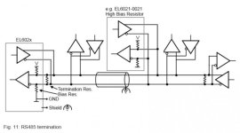
Regarding signal ground, Beckhoff EL6021 bus terminal (serial interface) has separate ground connection (https://www.beckhoff.com/english.asp?ethercat/el6021.htm).

Also, the terminal has integrated bias resistors: "The EL602x devices feature integrated bias resistors < 1 kOhm, which bring the bus lines to defined levels, even if the line is disconnected."

As for the resistors, I am not using typical RS-485 cable (Cat 5e UTP/STP) because I didn't have it there at the moment. Instead, I am using YSLCY 3x0,75 mm2 (screened control cable) for which I do not know characteristic impedance and which resistor would be suitable to match it.

Edit: forgot to mention before - Modbus error I am getting is "MODBUSERROR_CHARREC_TIMEOUT" (more common) and "MODBUSERROR_CRC" (as I stated, once per day, 1 erroneous reading per many successful ones). Any clues on the reason?

Bias.jpg
 
Last edited:
Thanks for the clarification.

Regarding signal ground, Beckhoff EL6021 bus terminal (serial interface) has separate ground connection (https://www.beckhoff.com/english.asp?ethercat/el6021.htm).

Also, the terminal has integrated bias resistors: "The EL602x devices feature integrated bias resistors < 1 kOhm, which bring the bus lines to defined levels, even if the line is disconnected."

As for the resistors, I am not using typical RS-485 cable (Cat 5e UTP/STP) because I didn't have it there at the moment. Instead, I am using YSLCY 3x0,75 mm2 (screened control cable) for which I do not know characteristic impedance and which resistor would be suitable to match it.

Edit: forgot to mention before - Modbus error I am getting is "MODBUSERROR_CHARREC_TIMEOUT" (more common) and "MODBUSERROR_CRC" (as I stated, once per day, 1 erroneous reading per many successful ones). Any clues on the reason?

CRC is checksum error, basically that some zero or ones have flipped during transmission.

Timeout error is that the slaves doesn't respond in time. Usually because there is noise on the line so they misintepret the actual message.


You cable is wholly inappropriate.

Standard RS485 cable is not Cat5E actually but network cable is close enough - if shielded. Cat6 would be even better. Ethernet cable like that is 100 ohm impedance so it should ideally have 100 ohm resistors.

Suitable RS-485 has to have a screen and be twisted pair to be able to resist noise.

You should only have bias resistors in ONE place on the RS-485 bus. Termination at BOTH ends.

Surely you can find a better cable. Here are Belden's RS485 cables: https://www.belden.com/products/industrial-cable/bus-cable/rs485.cfm

Usually you can use Belden numbers to find equivalent cables from other manufacturers.
 
Last edited:

Similar Topics

Hi! I communicate with an onboard communications board modbus RTU. I communicate with 5 VFDs (Parker AC10) and each has 4 calls of MB_Master. So...
Replies
19
Views
7,971
Hi We are running a control logix PLC system with controlnet. The controlnet has 12 nodes. Uses fiber in between the fiber repeaters . My main...
Replies
2
Views
1,818
Hi All, I wrote some code for a small hydro scheme a couple of months ago. Part of the project was to read data from a grid analyser via RS232...
Replies
0
Views
1,646
Apologies for not being the best IDEC programmer. I recently was doing some inspections on a site that had 3 FC6A IDEC processors. The issue is...
Replies
0
Views
38
Good morning fellow sea captains and wizards, I am being asked to do the above and obtain 4 values from each slave, I know about the MRX and MWX...
Replies
20
Views
201
Back
Top Bottom