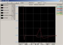
![]() ![]() ![]() ![]() ![]() ![]() |
||
![]() |
||
![]() ![]() ![]() ![]() This board is for PLC Related Q&A ONLY. Please DON'T use it for advertising, etc. |
||
![]() |
![]() |
#1 | |
Lifetime Supporting Member
|
Quick comparison of PID, PIDE, and PI instructions in RSLogix5000 ...
the following question was asked in a recent thread ... Quote:
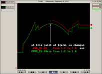
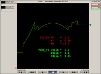
since the same question comes up quite often in my classes, I've put together a quick down-and-dirty set of experiments to demonstrate some of the major differences – and similarities – between these three "process control" type instructions ... please keep in mind that this is just an OVERVIEW – not a full discussion of all of the nuts-and-bolts material involved ... for one specific issue: most of these instructions have multiple setups which could substantially change their operation ... again, this is just an OVERVIEW of the basic ideas ... first let's compare the PID (Proportional Integral Derivative) instruction available in Relay Ladder Logic - with the PIDE (Enhanced PID) instruction available only in either Function Block or Structured Text programming ... the first thought that naturally pops into the beginner's head is that "enhanced" must somehow mean "better" ... well, the PIDE instruction DOES offer an "Autotuning" feature (if you've paid for the option) ... whether that particular feature is worth its price is debatable ... for some applications it works well – for others not so well ... (related thread) ... other than that, the PIDE does offer a LOT (some would say "too many") extra "controls" ... note that these controls are not necessarily going to control the PROCESS (flow, temperature, etc.) ... instead they're used to change the modes, and status settings, etc. of the PIDE instruction itself ... the last time I counted there were 167 settable "parameters" inside that PIDE function block ... let's do the math on that ... if we decide to just "call out" the name of each one of those parameters – and give just a 30 second explanation of how each parameter BASICALLY works – then we're talking about over 80 minutes of time which would be required just for that little "getting acquainted" session ... about an hour and half just to list the names – and the BASIC functions ... but that still begs the honest question: will I get BETTER CONTROL over my process by using this "enhanced" PIDE instruction instead of a "regular old-fashioned" PID? ... well, let's see ... in the screen shot below, the RED trace shows the output of a PID instruction – compared to the GREEN trace produced by a PIDE instruction ... although the tuning settings APPEAR to be different – the values shown have been calculated to give the same "tuning" for both methods of control ... TIP: the "time related" functions (Integral and Derivative) are "off" by a factor of 60 ... that's because this configuration of the PID uses SECONDS – and the PIDE uses MINUTES ... IMPORTANT! ... the signal for the INPUT is NOT being shown in this series of graphs ... the basic idea is to provide a repeatable "dummy" signal (I call this a "profile") as the input to BOTH of the instructions simultaneously ... in other words, the PID and the PIDE are both "looking at" the same input signal – and each instruction is then calculating its own OUTPUT signal ... but NEITHER of the two outputs is actually in control of the process ... specifically, the input signal just ramps up and down – regardless of what the controls (PID and/or PIDE) do in response ... so in this "test" setup, nothing that the PID or PIDE controllers (bless their little hearts) can do will alter the INPUT signal ... this allows us to perform a side-by-side COMPARISON of how the two instructions perform ... I've been using this same "dummy input" technique for years to learn about – and to teach – certain PLC concepts which are exceedingly hard to understand using any other method ... yes, eventually you'll HAVE to have a complete "feedback loop" available in order to actually practice "tuning" – but that's another fish – to be fried another day ... now back to our story ... in the screen shot below, we can see that the PID and the PIDE are both giving essentially the SAME RESPONSE to the dummy "profile" input signal (not shown) ... true, there ARE some sections where the PID's red trace deviates from the PIDE's green trace ... those deviations are the result of a "filter" applied to the Derivative component – which is built into the (old fashioned) PID – but is NOT incorporated in the (new fangled) PIDE instruction ... so ... as far as I'm concerned, I'm not seeing that the "enhanced" PIDE has any ability to perform "better control" over a process than the UN-enhanced PID ... but ... maybe the optional "autotune" feature is attractive to you – or maybe all of those extra "bells-and-whistles" controls could come in handy – or maybe you just love programming in Function Blocks ... whatever ... if you've got a REASON to go with the PIDE – then go for it ... personally I don't usually enter into the debate about which method of control is "better" ... but then I'm invariably just teaching my students how to deal with "what they've got" back at the plant ... specifically, my students are usually maintenance technicians – who don't get to choose their battles ... it usually boils down to this ... once upon a time, a certain "programmer" put this PIDE thing in our plant's program – and now we've got to understand enough about it to get the pump back into operation again ... when you're troubleshooting a $y$tem with the boss breathing down your neck at 3:00 o'clock in the morning, it's hard to be impressed by 167 "extra" parameters – and wondering if one of those fancy settings just happens to be keeping the pump from running ... anyway ... as the chart below shows, I suppose that the PID could actually be considered to give a "smoother" control over the Derivative action than the "enhanced" PIDE ... but for my money, it essentially it looks like a dead heat in the overall "ability to control" competition ... .
__________________
|
|
![]() |
![]() |
#2 | |
Lifetime Supporting Member
|
going further into the PID vs. PIDE comparison ...
here is one of the advantages that the "book" mentions for the newer PIDE over the older PID instruction: Quote:
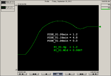
in the chart shown below, we've made an "on the fly" change to the proportional gain for each instruction - to compare how the PIDE and the PID methods handle this type of operation ... the "bump" to the PID's red trace is easily seen ... and true to the book's word, the PIDE's green trace has no such "bump" when subjected to exactly the same modification ... .
__________________
|
|
![]() |
![]() |
#3 |
Lifetime Supporting Member
|
besides the PIDE (Enhanced PID) instruction, RSLogix5000 offers the PI (Proportional Integral) instruction – which can also only be used with either Function Block or with Structured Text programming ... specifically, the PI instruction cannot be used in Relay Ladder Logic ...
the PI instruction offers an interesting feature which is not available with either the PIDE or the PID instructions ... you can use the "gains shaping" feature to alter the Proportional Gain and/or the Integral Gain – based on the amount of "error" (deviation from the setpoint/target) that the instruction "sees" ... before we perform a simple "gain shaping" experiment, take a look at the chart below ... here we're comparing the "normal" response of a PIDE instruction – with the "normal" response of a similarly tuned PI instruction ... again the values of the settings are different since the two instructions use different units for their gains – but obviously there is no "better control" available with either of the instructions – at least at this stage of the game ... specifically, the responses are so similar that the PIDE's white trace is almost completely obscured by the green trace of the PI instruction ... naturally we had to turn the PIDE's Derivative action off (0.0 setting) to give the PI a fighting chance ... but once we leveled the playing field, the PI has no trouble keeping up with the "enhanced" PIDE ... .
__________________
|
![]() |
![]() |
#4 |
Lifetime Supporting Member
|
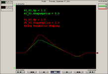
the chart below shows two PI instructions ... for the purposes of this demonstration, each PI is using ONLY Proportional action – specifically, the Integral action has been turned off for both of the instructions ... this will make it easier to identify the "gain shaping" feature ...
the GREEN trace shows the "normal" response of a "Proportional only" controller ... the 0.0 setting basically turns OFF the "shaping" feature ... the RED trace shows the response of the Proportional action being "shaped" by the 2.0 setting ... in SIMPLEST terms, once the error (the deviation from the desired target) reaches a certain point, the "shaping" comes into play ... this could be regarded as "cranking in some extra" proportional action – but only when it's needed ... I suppose that in some applications, this might come in quite handy ... the Integral action can also be "shaped" in the same way – it's just harder to identify its response on the chart ... hopefully this thread will shed some extra light on the BASIC differences between the PID, the PIDE, and the PI instructions available in RSLogix5000 ... party on ... .
__________________
|
![]() |
![]() |
#5 |
Member
![]() ![]() Join Date: Apr 2005
Posts: 54
|
I created an AOI that encapsulates the PID instruction and incoporates the bumpless adaptive gain changes capabilities.
|
![]() |
![]() |
#6 |
Member
![]() ![]() Join Date: Mar 2008
Location: Northern Illinois
Posts: 145
|
Ron, thank you for going through this exercise. I wrote some code to simulate the motor I will be controlling so I could test my speed control loop, and could not get the PID and PIDE instructions to provide the same performance. I hadn't picked up on the I and D gains being off by a factor of 60, once I adjusted the gains appropriately they now track each other perfectly.
Depending on your control loop speed, the scan time of the PIDE could be a concern. I think I read that it is around 2x the scan time of a PID instruction. I'm running my simulated speed loop at 10ms right now, so scan time is important, but some of the commands like integral hold on the PIDE are nice to have. Edit: I just looked in the execution time manual, and for an L62, the PIDE takes 147us to execute, whereas the PID is between 55 and 70us depending on integer/real and what mode it runs in. Last edited by Paul351W; October 3rd, 2012 at 01:12 PM. |
![]() |
![]() |
#7 |
Member
|
Does the variable gains only depend on error? If so that is SO WRONG. Changing the gains should be done in response to the system changing, not errors. Changing the gains as a function of something in the system changing is useful. One can change the PID gains on-the-fly can't they?
__________________
"Living is easy with eyes closed, misunderstanding all you see...." Strawberry Fields Forever, John Lennon |
![]() |
![]() |
#8 |
Member
![]() ![]() Join Date: Mar 2008
Location: Northern Illinois
Posts: 145
|
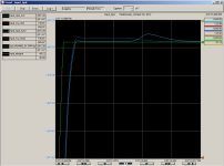
I've done some more playing around with my simulator, and I can recreate a condition where the PIDE does something that I can't quite figure out. On a speed increase command, the PID and PIDE output (and calculated speeds) track each other until just after they reach setpoint, the PID overshoots slightly more. After about 500ms, the PIDE increases output temporarily, causing a brief overshoot further above the setpoint. The dark blue is PID controlled speed, light blue is PIDE controlled speed, orange is PID output torque, and red is the PIDE torque command. Light Green is the ramped setpoint.
I've attached the images of the same event. |
![]() |
![]() |
#9 |
Member
![]() ![]() Join Date: Mar 2008
Location: Northern Illinois
Posts: 145
|
I figured out that the behavior above was related to my limiting the min and max CV value based on shaft speed. The system was overshooting, then the integrator had to wind down until it got below the max CV setting to reduce the shaft speed to setpoint.
|
![]() |
![]() |
#10 |
Lifetime Supporting Member
|
glad you got it figured out ...
TIP: if you have to post any more graphs, PLEASE double-click the dark blue icon in the upper left corner and choose a better color than dark-blue on black ... why on earth do the Rockwell guys always use that combination as the default? ...
__________________
|
![]() |
![]() |
#11 |
Member
![]() ![]() Join Date: Jul 2017
Location: Italy
Posts: 2
|
Very interesting, hope this thread it's not so old: since I'm going to perform a similar test to compare two PID algorithm soon, I'll be grateful to know what kind of "Test Input" you used in this test... just curious. Thank you very much!
|
![]() |
![]() |
#12 |
Member
|
What is the purpose of comparing to Rockwell PIDs?
What kind of system are you trying to control. That makes a huge difference. Are you doing this for a class?
__________________
"Living is easy with eyes closed, misunderstanding all you see...." Strawberry Fields Forever, John Lennon |
![]() |
![]() |
#13 |
Member
![]() ![]() Join Date: Jul 2017
Location: Italy
Posts: 2
|
I'm not going to compare two Rockwell PID... nor compare them a Rockwell system too. Let's say I have two PID codes/FB/AOI and I'd like to compare their behaviour, finding differences on how they work (i.e. effects on modifying their parameters)
|
![]() |
![]() |
#14 | |
Member
|
Quote:
My question is: Does anyone have experience on implementing a adapative gain in real world machines? Did you use the parabolic curve (like this PI instruction) or a linear one? Is it really a big difference in terms of control? I want to control temperature and pressure (i know its very vague and it depends on a lot of other factores). Best regards crawler009 Last edited by crawler009; March 1st, 2018 at 03:47 AM. |
|
![]() |
![]() |
#15 |
Member
![]() ![]() Join Date: Mar 2006
Location: PA
Posts: 21
|
Thanks for that tip! I used Autotune to get the P, I, D parameters then entered them into my PID, and it was driving me crazy why my PIDE was rock solid but the PID was so unstable. It's because my I & D were off by a factor of 60. It slipped my notice that the time parameters were different. Thanks Rockwell for not making them the same!
Last edited by Russff; June 7th, 2018 at 02:26 PM. |
![]() |
![]() |
Bookmarks |
Currently Active Users Viewing This Thread: 1 (0 members and 1 guests) | |
Thread Tools | |
Display Modes | |
|
|
![]() |
||||
Thread | Thread Starter | Forum | Replies | Last Post |
RSLogix 5000: PI vs PID vs PIDE | Paul351W | LIVE PLC Questions And Answers | 5 | September 29th, 2012 10:32 PM |