Timer on ML1000 wont get /DN

Aabeck

Member
Join Date
Feb 2013
Location
Detroit
Posts
1,860
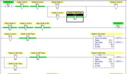
I have come across something I've never had happen before. I have a ML1000 with RSLogix500 been using for years. The first pic shows Mode G activating when it should & when the Mode G control timer ends, Mode G stays on until timer T4:2 is DN. However T4:2 NEVER gets /DN & Mode G never ends. I have T4:2 holding itself on with the /EN so it should stay on until /DN clears the line.

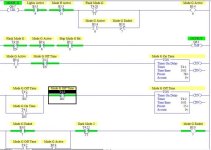
What I had to do is in the 2nd picture trap the /DN & set a B3 bit to end Mode G, and that works. So why wouldn't T4:2 get /DN on it's own???

EDIT:
Just looked at it & I tried to zoom in, but the pics look a little small, gonna try & post better pics.

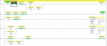
Mode G Wont End.jpg Mode G That Ends.jpg
 
Better pics I hope.

Normally T4:2/DN should stay on a full scan until the timer is reset the next scan, 3 lines after Mode G ends.

Mode G Wont End.jpg Mode G That Ends.jpg
 
But that will only jump to the output section if Mode G is NOT active & has properly ended, which it's never doing in the 1st example.

And in the 2nd example that works it has the same JMP line.
 
Last edited:
You're right about the JMP - sorry I didn't look at it long enough.

The funny thing about the diagram is you didn't change anything on T4:2 rung. And, clearly, it's getting done if it's causing B3:0.7 to turn on.
Did you do any trending or set a trap (on WONT END layout) to ensure that it wasn't turning its DN bit on?
There could also be an issue with the EN bit vs. TT bit that you could have used in its place.
Quite the mystery, indeed!
 
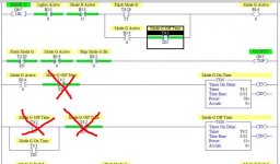
I suspect that the XIO T4:2/EN in the 3rd rung is resetting T4:1. While I'd expect the XIC T4:2/EN to already be on to maintain T4:2 in the following rung, the lack of the XIC T4:1/DN branch might make you lose the latch. :confused:

Unless you NEED T4:1 to reset when T4:2 starts, I would just let T4:1 remain DONE, and eliminate the extra contacts (see attachment).

🍻

-Eric

Mode G Wont End.jpg
 
Eric,
T4:1 needs to be shut off, as the 2 timers are a flip-flop that repeat while Mode G is active for about 8 seconds - and as expected they work. The problem is that the T4:2/DN is not staying on a full scan & I checked the following:
No double use of the timer in the program.
No RESET command for the timer anywhere.
No checking & clearing the /DN bit for the timer in the program.

And I have other modes in the program that are all controlled the same way & only T4:2 of all the timers is being a problem.

danatomega:
I originally was using the /TT bit for T4:2, but thought maybe that was clearing the timer when it stopped timing & was clearing the timer so the /DN wouldn't be on the later, so I changed it to XIC /EN & XIO /DN.
 
What I think might be happening is that when T4:2 is going done, because you have an XIO that is looking at the done bit for T4:2, when it goes done the rung goes false which will make the EN and DN bits for T4:2 go low. In other words, when T4:2 goes done, the XIO “T4:2/DN” forces the rung to go false, causing T4:2/DN to go low thus allowing the rung to go true again restarting T4:2. T4:2 is going done it’s just happening so fast you can’t see it.
If you create another rung right below T4:2 and have T4:2/DN latch a bit. You could then use that for the XIO instead of T4:2/DN but you’ll then have to come up with a way to unlatch it.
 
Firejo,
The check for T4:2 going done is before the timer instruction and does not reset the timer until the next scan. The control of T4:2 does work, but 3 lines before that it's looking for the same/DN bit to end Mode G & that is never ending in the 1st example (& T4:20 that times Mode G IS turning off properly).

Just for some strange reason the /DN bit seems to be clearing itself without any other control of it.
 
It's got to be something else in the logic. I put the illustrated fragment (with a few address changes) into the Starter Lite emulator and it runs as described.
 
I checked:
T4:2 is only used once
No RESET command for T4:2 anywhere
No checking & clearing of the /DN bit (for any of the timers)
The JMP only activates AFTER the mode is inactive & then only after one full scan to reset everything & then set a Skip Bit at the end of the ladder

(Unfortunately the customer has paid for all rights to the program & I cannot publish it in any format per the contract)

And the customer spec'd the JMPs to improve the scan time.
 
Last edited:
Aabeck said:
Unfortunately the customer has paid for all rights to the program & I cannot publish it in any format per the contract

That's a shame.

I'd perhaps try replacing all instances of T4:1 and T4:2 with different timers, and in fact to be completely sure, from a whole different register - e.g. create a new register of Timers like T99, and use T99:1 and T99:2. If the problem stays, it's a coding error somewhere. If the problem goes away, well, I'd be starting to trawl through the program looking for indirect addressing and COP instructions with longer than expected lengths. Things like that.
 

Similar Topics

Could anybody fetch me an idea how to make analog input 0-10v to control preset of a timer in ML1000-ML1200 (with slc500 I move SCP scaled...
Replies
3
Views
1,850
Hi all, I have a simple question that I have overcomplicated and gotten stuck on. I have a variable, we can call it "light" that I need to stay...
Replies
4
Views
298
Question to anyone with ideas about my thoughts on upgrading a very vintage timer, which is being used to switch between 2 5hp domestic water...
Replies
14
Views
431
why my timer only executes once here? After first time i use it, ET stays at 0ms all the time. It is in FB
Replies
5
Views
302
Good morning guys, I'm searching for a Timer relay which accomplishes the "flasher" condition in the photo attached, however, I need the ability...
Replies
2
Views
553
Back
Top Bottom