Learning by Doing

pstephens

Member
Join Date
Sep 2004
Location
Indiana
Posts
342
Hi Folks,

I’ve been hanging around here for several months now, learning from the discussions, but not really feeling qualified to make a comment. I’ve been designing industrial machinery at various companies for well over twenty years -- everything from a fixture for gluing chicken feathers to wooden darts, to a machine for testing burial caskets by shaking them violently up and down. A little over a year ago I decided to go into business for myself, hiring my design and CAD services out to various industrial clients. It was slow getting started, but the past six months have been fairly busy. The reason for this post is that I think I’ve gotten myself in over my head with my latest project.

My educational background (and most of my work experience) is in mechanical engineering, though I have designed quite a few machines equipped with both relay and PLC control systems. In these instances, if more than a couple of relays was required, I would farm out the control design to an expert. For my part, I would develop a detailed list of inputs and outputs, as well as a detailed operational sequence for the person designing the control system. Sometimes they would build the panel, sometimes I would build it to their specs. So, I’ve been around this stuff for quite a while, though I’ve yet to design a complex control system from scratch. I’ve made minor modifications to others’ programs, but that doesn’t take a lot of smarts.

Anyway, I recently got the job of designing a fairly simple machine to automatically feed 1/8” dia. spring wire from a coil and cut it to specific lengths. The cut wires are used as stiffeners in those accordion-style covers often seen on scissors-lift machinery. Normally, I would have hired a controls designer to do the controls, but since I design so many of these kinds of machines, I thought why not at least try and do it myself? Even if I don’t make my usual hourly rate, I would be getting valuable experience that would pay off down the road. But now that I’ve actually gotten into the design, I’m starting to think that maybe I bit off more than I can chew (let alone swallow). utoh

I may yet have to call in an expert, but I plan to at least give this a decent effort. I’m not here looking for someone to design my program. The depth of knowledge and experience of the people on this forum is staggering, and my hope is that some of you guys will be able to offer comments, hints, suggestions, etc. to keep me heading in the right direction, and perhaps answer the occasional question as I go along.

This post is just a preamble, and I will come back shortly with some specifics, as I want to break this up into manageable bites. Thanks in advance for any replies.

Pstephens
 
Last edited:
Greetings Pstephens,

and welcome to the forum ...

I will come back shortly with some specifics

we look forward to hearing from you again ... please include specific model numbers, I/O lists, and as much detail as you can about how the machine is supposed to operate ... the more detail you give us to work with, the better the advice will be ...
 
Welcome, Pstephens. I too am a converted (corrupted?) mechanical engineer.

It looks like you have the basics down. It would seem to me the biggest question is the device you are going to use to measure the wire. There are a lot of ways to do that, most of which I have no idea about because I don't know squat about motion control. But the guys here do! I'm sure you'll get a lot of help.
 
Well you've come to the right place...I can feel my ego growing already...

1st of all the mechalical design is important. There are many past threads reguarding measuring and cutting a wire or tube etc.. but it seems your dealing with a preformed coiled product, which makes it far less strightfowrard from a mechanical point of view. If your using an AD PLC of some type you may be in good luck. Buried someware in my war chest I've got a program to feed, measure, stop and cut etc.. When you can provide more details I'll go and look for it..

Mike.
 
The Existing System

Hi again,

Thanks for your replies so far!

My customer on this job is currently running small batches of this 1/8” dia. spring wire in a more-or-less manual fashion. Basically, an operator pulls the wire from a 100 lb. roll mounted to a crude turntable affair on the floor, and feeds it thru the blades of an air-powered shear, to an adjustable stop. Then he actuates a hand valve to shear off the part. This process is repeated until the desired quantity of parts has been run. (There’s an air-actuated counter on the shear.) Here’s a picture of what it looks like:

CURRENT.jpg


The customer is interested in a machine that will automatically feed and cut parts to a preset length (12 to 144 inches) and quantity. He also wants the machine to be able to accommodate a 500 lb. roll of wire. The existing 100 lb. rolls need to be re-rolled from 500 lb. rolls by the steel vendor, at a higher cost.

A number of factors about this application made me want to take it on:

1) The guy I’m dealing with (the owner of the company) is easy-going and reasonable.

2) This is an off-line operation -- not tied into any large, automated process lines.

3) I can incorporate the existing shear unit into my design. It’s an almost absurdly simple, intrinsically-safe little device that shears the wire quickly and easily, with virtually no burrs. So, at least I don’t have to re-invent that part of the operation.

4) The tolerance on the length of the sheared parts is fairly loose: +/- 1/8 inch.

5) The customer is in no particular hurry to get the machine completed. He’d like to have it running by the end of the year, but is not adamant about that.

The big disadvantage was the amount of money he was willing to spend on this project. My normal approach to an application like this would be to hire a controls house that specializes in motion control applications, probably going with a closed-loop servo motor integrated into a PLC control system. But I knew from experience that I could never meet the customer’s price, freighted with that cost. Needing the work, and having a nagging desire to get more into controls design, I hit upon the idea of using an open-loop drive system, and designing the control system myself. Given the favorable factors listed above, I figured I could learn enough about programming to do this small project, and get paid something in the process. I’m not sure if I made a good decision, but it’s academic now, since I got the order for the machine.

I’ve spent a good deal of time reading the archives here, and I haven’t read many positive things about stepper-motor drive systems. It seems that designers are always getting goaded into using them by their relative simplicity and low cost, and then paying the price in the form of missed steps, lack of torque at speed, and a host of other idiosyncrasies associated with an open-loop stepper system. In this case, I don’t believe I really have any other choice. Oriental Motor makes a closed-loop stepper system (“Alpha-Step”), but it compares in cost with most servo systems I’ve seen. I’m hoping that if I go with a fairly robust motor (NEMA 42, or a large 34 frame), the relatively loose length tolerance will make the system practical. (Yes, my butt’s really hanging out there on this one!)

In effect, my design for this machine is similar to the feed system on a wire-feed welder. The wire roll will be mounted (axis vertical) on ball bearings, with an adjustable friction brake to control the build-up of inertia. From there the wire will go through a hardened guide block that also incorporates a prox switch for sensing wire presence. After that: an air-powered clamp to hold the wire securely in position during cut off. The drive mechanism would consist of four hardened, contoured rollers, all positive-drive (no idlers), and coupled to the motor by gearbelt. From there, the wire enters the blades of the existing shear unit, incorporated into the new machine. Prox switches will sense the limits of the shear unit’s air cylinder, and another prox will sense the presence of wire on the downstream side of the shear blades. Here’s a close-up of the shear unit:

SHEAR.jpg


I’ve been trying to educate myself about PLC programming over the last several weeks. I purchased and studied Phil Melore’s “PLC Tutor” book, and also got a nifty PLC simulator program from “Knoware”, which includes a nice tutorial. I also downloaded the evaluation version of DirectSoft, since I will be using mostly AD components.

I hope all of this gives you a pretty good idea of the scope of this project. I’ll be back shortly with some control system specifics.
 
Re: The Existing System

pstephens said:
I also downloaded the evaluation version of DirectSoft, since I will be using mostly AD components.

1st of all bear with me; Im a terrible speller and their's no spell check on the posting page of the forum.... :rolleyes:

Since your going to use AD equipment, I'd suggest that you go to the www.automationdirect.com website and go ahead and buy the working sofware and PLC and get at it that way. I'm sure Phil has great materials but the AD manuals are more spicific for the AD PLCs that you'll be using and it would be a little bit of a short cut on the learning curve. So far it seems to me that a DL-06DR may work well on your project, and if not it's no big loss as it's inexpensive, and could be used elswere some other time. At any rate it's a great learning tool. I would also suggest getting the display ($50.00). I know some guys think it's usless becaue you cant use it to input data, but you'll be able to display important info with out too much trouble.

I'm not sure if a stepper is going to provide enough power to pull on a wire comming off a 500lb reel. Hopefully somebody else expieranced in steppers might pipe in and lend some comments on this.

My first impression is that you can use the existing shear, but will have to replace the button with a solinoid valve.

I see the wire being pulled off the reel by a pinching hardened knerled roller set (driven by a multispeed motor) and pushed through the sheer. The driving rollers would be tensioned togeather by a strong tension spring with a release for reloading and new real. The rollers would also have an quadature encoder mouned on the roller shaft to provide distance, direction and speed feedback to the PLC (inputs x0 and x1 on the DL-06). I say direction in the event that there's an overshoot so the machine can back up a little if necessary.

The real inportant part of the project is comming up with a good mechanical design. No amount of programming is going to resolve issues with poor mechanical aspects of the machine. Right away I could imigane potential issues with the feed reel continuing to unwind after the feeder has stopped, a possable undersized drive mechinizem, what happens to the cut wire once its cut and so on.

So I posted below a quick shopping list for now. I'm not sure of the accuracy you need but with a 2" round drive roller you'll get about 1/8" resolution with a 100ppr (pulses per revolution) encoder. For better resolution I picked a 360ppr encoder, but it's really your choice to make.

Here you go.. (it's only a suggestion)

wire cut off plc.jpg
 
elevmike said:
If you're using an AD PLC of some type you may be in good luck. Buried someware in my war chest I've got a program to feed, measure, stop and cut etc.. When you can provide more details I'll go and look for it..

Hi Mike,

That's great! Yes, I plan to use AD components wherever possible. That's another good thing about this customer -- he's not married to any particular brand. The only other PLC systems he has in the plant are A-B, but he understands that he can't afford them on this project, and has no problem whatsoever with AD.

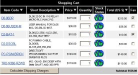
Here's what I've ordered so far:

D0-06DD1 DL06 PLC
D0-06USER-M User Manual for DL06
D2-BAT-1 Battery
D2-DSCBL PC Programming Cable
EZ-220P EZ-Text Keypad Panel
EZ-2CBL EZ-Text to PLC Cable
EZ-TEXTEDIT EZ-Text Programming Software
EZTEXT-PGMCBL EZ-Text Programming Cable
FA-24PS 24VDC Power Supply for EZ-Text
PC-PGM-BRICK DirectSoft Programming Software
USB-RS232 USB to RS-232 Adapter Cable

I made the decision to order this stuff right away so I could start getting the feel of the hardware, and play around a bit. Also, I can study the manuals with the benefit of having the actual item in front of me.
 
Here's some Free advice (worth every penny)
That looks like a great project.
Is the wire size always going to be the same?
I bet you can Use a switch like This on the wheel that feeds the wire and forget the stepper motor.
Count the sprockets you may be surprised how accurate you can get.
Especially with those loose tollerances.
Good Luck!
 
Looks like you and I were posting at the same time... so please take a look at my post above.

I would have ordered the Relay output (DL06DR) this model has a built in 24volt aux power supply that can be used for the EZ, encoder, inputs etc.. Conventional 110vac power requirement. The relay outputs are much more versital then the DC outputs, and can handle more current etc..

You wount be able to operate coils large relays or solinoids from the DC outputs, but you can operate almost anything from the Relay outputs.

EZ touch display is a good idea.

You can down load "Example Programs" from ADs tech support section of their website. Take a look at them.


gbradly,

I dont get how that is going to measure wire length? How do you mean to apply it?
 
I dont get how that is going to measure wire length? How do you mean to apply it?
Well
Cicumference of a Wheel is Pi times diameter or 2PiR.
If a wheel that feeds the wire is 2" in diameter then 1 Rev will feed 6.28 inches of wire.
I guess you are correct you can't count the spokes, but if you had Small holes or teeth at 1/8" spacing. (it would take about 50 on a 2" Dia Wheel)
Just a thought to save on the PLC.
Does a stepper motor require an analog input/Ouput?
 
Re: Re: The Existing System

Hi Mike,

Looks like our posts "crossed in the mail", but thanks for all the helpful advice. I hope I didn't jump the gun in ordering some of the major components already. I opted for DC inputs and outputs on the DL06, since I thought they might be more compatible with a pulse output. But I'm kind of guessing here.

elevmike said:
...the AD manuals are more spicific for the AD PLCs that you'll be using and it would be a little bit of a short cut on the learning curve.

My thoughts exactly!

I would also suggest getting the display ($50.00). I know some guys think it's useless because you can't use it to input data, but you'll be able to display important info with out too much trouble.

I thought about getting the display, too, but I've also read so many negative comments -- people thinking it would do things that it turned out not to be capable of. I'm keeping an open mind on this. What are some of the specific advantages?

I'm not sure if a stepper is going to provide enough power to pull on a wire comming off a 500lb reel.


This is one of my biggest concerns, and kept me on the fence for a long time, about even bidding on this job. A saving grace in this application is the slow speed requirement -- 8 to 12 in/sec -- which translates to the fully-loaded roll rotating at somewhere between 6.5 to 10 RPM at maximum feed rate, which, when plugged into the inertial moment calculations does not add up to a large torque requirement at all. I'm planning to provide an adjustable friction brake on the unwind reel, to prevent momentum build-up. This will increase the torque requirement, but will tend to counteract the tendency for the supply roll to "run away" when the feed motor stops. A compromise setting would have to be arrived at.

I see the wire being pulled off the reel by a pinching hardened knurled roller set (driven by a multispeed motor) and pushed through the shear. The driving rollers would be tensioned together by a strong tension spring with a release for reloading and new reel.

My first impulse was also to use a knurled drive roller. Ultimately, I came to the conclusion that a knurled roller would prove troublesome down the road. Because this is a hardened spring wire, the knurls would have to be significantly harder to have a decent "bite" and long life. And that makes them brittle and prone to chipping on the sharp edges. The spaces between the knurled teeth become clogged with tiny shards of metal, decreasing their penetration, and also changing the effective circumference of the drive roller. Also, the customer is interested in minimizing any serrations on the finished part, as they must be slid into a sewn pocket at assembly, and friction is sometimes an issue. I am leaning toward using four driven wheels, each contoured to closely fit the wire diameter. This maximizes the rollers' contact with the wire, and spreads out the "pinching" force over a larger area.


The rollers would also have an quadature encoder mouned on the roller shaft to provide distance, direction and speed feedback to the PLC (inputs x0 and x1 on the DL-06). I say direction in the event that there's an overshoot so the machine can back up a little if necessary.

This is something I would like to consider in more detail. My first reaction to the idea of a closed-loop drive system was that this project could not bear the cost, and that it would greatly complicate the control system (further adding to the cost). But that may be just my own fear and ignorance. I'd like to learn more about how an encoder would be integrated with the control system.

I'm not sure of the accuracy you need but with a 2" round drive roller you'll get about 1/8" resolution with a 100ppr (pulses per revolution) encoder. For better resolution I picked a 360ppr encoder, but it's really your choice to make.

The accuracy requirement is +/- one-eighth inch. on the sheared length. I'm leaning toward a drive roller with around a 6" driving circumference (approx 1.91" dia.), and a gearbelt pulley ratio of 1:3 between motor and drive rollers. Most of the stepping motors I've looked at have a native resolution of 200 steps/rev., so the wire travel for each motor step would be .010". Or .005" with half-stepping (if my math is correct!) This translates to a fully-accelerated motor RPM of 720, which is high enough to keep the motor running fairly smoothly, without getting too far into the steep torque drop-off that most speed-torque curves seem to exhibit at higher RPM's.

I'd like to consider this encoder idea further...
 
Last edited:
elevmike said:
I would have ordered the Relay output (DL06DR) this model has a built in 24volt aux power supply that can be used for the EZ, encoder, inputs etc.. Conventional 110vac power requirement. The relay outputs are much more versatile then the DC outputs, and can handle more current etc. You won't be able to operate coils, large relays or solenoids from the DC outputs, but you can operate almost anything from the Relay outputs.

Shows how much I know... :oops: I wonder if I can exchange it?
 
Welcome pstephens!

A carefully selected stepping motor still remains a pretty good choice in lots of projects. I have been in the field for years and the number of applications always seems to be endless whatever you think about. Anyway, mechanical skills and background are serious assets here and your customer is really in good hands. The load inertia plus your drive mechanism should deserve a quite strong motor. Did you experience the required starting torque? If you plan to keep working in NEMA34, ask PacSci for quotations among their Sigmax K3x series (select 8 leads / K types). As a matter of fact, extended prices should reflect some hugely extended capabilities. But this will allow you to get high torques while dealing with mid-range voltages (less than 90V)/currents and a low-cost homemade power supply (compared to bigger motors often requiring up to 130/160VDC). Open frame OEM drives up to 12Amps or metal housing types up to 12/14 Amps may be easily found. As far as no micro-stepping modes are involved, any PLC with a dedicated pulse function (solid state output is mandatory!) including manageable accel/decel will suit this project with peripheral I/Os rather than an indexer.

gbradley:
Basically no analog I/Os are required for steppers control.

Laurent
 
Here is a first go-around at a detailed operational sequence (It was in writing this that I began to get an idea how much more complicated this project is than I originally thought.) This is of course based on using an open-loop stepper system, which is a debatable issue, at this point. I’ve also included a basic machine layout, showing the relative locations of the major components. Also, a preliminary operator panel layout, based on using the EZ-Text 220P.

MACHINE.jpg


PANEL.jpg


Sequence of Operation

1) Load wire roll on machine

2) If needed, pull out START/STOP switch (also pull out START/STOP switch on remote E-Stop station, if necessary)

3) POWER indicator light comes on

[I plan on using a master control relay that will control power to the outputs. The PUSH TO STOP/PULL TO START switches, in series, will control this relay]

4) Move MODE selector switch to LOAD position

5) LOAD indicator light comes on

6) Move CLAMP selector switch to OFF position -- SVI is de-energized

7) Move PINCH ROLLER selector switch to OFF position -- SV2 is de-energized

8) Manually feed wire from roll, through wire clamp, pinch roller unit, and shear, leaving approx. 6” sticking out from blade

9) Move CLAMP selector switch to ON position -- SV1 is energized

10) Push CUT button to shear off end of wire -- SV3 is energized while button is held in (the CUT button has no function in RUN mode)

[this establishes a “zero” position for the RUN mode operation]

11) Move MODE selector switch to RUN position

12) When RUN indicator light comes on, press RESET, but only if this is a new program, and you are not resuming a previous program that was halted due to running out of material.

13) First line of display reads: ENTER PART LENGTH

14) Enter part LENGTH desired, using keypad -- number entered appears on second line of display

15) Push ENTER

16) First line of display reads: ENTER QUANTITY

17) Enter quantity desired, using keypad -- number entered appears on second line of display

18) Push ENTER

[Note: Pressing ESC before entering length or quantity will clear the number from the display so that another may be entered]

19) Push START to begin RUN cycle -- Display reads: CYCLE IN PROGRESS

20) CLAMP releases -- (SV1) is de-energized

21) PINCH ROLLER is activated -- (SV2) is energized

22) If LS1 and LS4 are made, and LS2 and LS3 are unmade, the LENGTH entered is multiplied by a constant, and the product number of pulses is sent to the stepper motor, modified by a pre-determined acceleration/deceleration profile. [Maximum feed rate is 8 to 12 in/sec.]

23) After a 1 second delay, LS2 must be made, or cycle is aborted and returned to the state existing immediately after step 18 [This is to assure that wire is not hung up in the shear blade, or elsewhere]

24) Wire is fed through machine until the prescribed number of pulses has been sent to the stepper motor, at which time the CLAMP (SV1) energizes

25) After a 1/2 second delay [to assure that clamp is fully seated], the SHEAR (SV3) is energized to cut off wire

26) When LS3 is made, SV3 is de-energized, retracting the SHEAR cylinder

27) When LS4 is made [indicating that the SHEAR cylinder has fully retracted], the program subtracts 1 from the QTY in register

28) Examine resultant QTY. If QTY is greater than zero, program repeats steps 20 thru 27

29) If QTY equals zero, program stops, and display reads CYCLE COMPLETED


Exceptions:

A) If the PAUSE button is pressed during an automatic cycle, the cycle will stop after the next full part is completed (step 27). The QTY remaining will stay in memory, and the display will read CYCLE PAUSED until START is pressed, at which time the cycle resumes.

B) If RESET is pressed at any time during RUN mode, the current LENGTH and QTY settings are erased, and the program returns to the state existing in step 13

C) Pushing the PUSH TO STOP/PULL TO START button, either on the main panel or the remote station, removes all power from the control system. All outputs are immediately de-energized, and any QTY/LENGTH entries are erased.

D) If at any time during an automatic cycle LS1 becomes unmade (indicating a “material out” condition), the motor stops immediately, and the current part cycle is aborted, though the current QTY and LENGTH settings are retained in memory. The FAULT indicator light comes on, and the display reads MATERIAL OUT. At this point the operator moves the mode switch to LOAD, and after removing the leftover piece of wire from the machine, proceeds with steps 1 thru 11, but does not press RESET. First line of display reads RESUME PROGRAM? and the second line reads PUSH START. Operator presses START and program proceeds with steps 20 through 29.


I haven’t written a complete list of Inputs and Outputs yet, because I’m a little fuzzy how these are assigned with regard to the EZ-Text panel. I understand enough to know that the selector switches, prox switches, etc. become X0, X1, X2, etc., and that the solenoid valves, stepper drive, etc. become Y0, Y1, Y3, etc. outputs. But how are addresses assigned to the control elements that are part of the HMI panel? Maybe this will become clearer when I get into the manual.

But that’s for tomorrow, I’m heading off to bed!
 
Last edited:

Similar Topics

Hello everyone. I am currently doing a project to teach about ethernet topologies such as ring or bus. For example. But instead of using an...
Replies
8
Views
4,334
Although I did not title it as such the last chapter would have been the PID. Learned a lot will give the details in that post. SO on to the...
Replies
20
Views
10,552
I've gotten to the learning curve where I can program a call for pump to come on at set point but I'm not sure how to turn the same pump off when...
Replies
1
Views
117
I want to pick up an Allen Bradley PLC so I can practice writing programs. I have 10 years as a maintenance tech and a good understanding of...
Replies
8
Views
228
Hi all, i have started a new chapter in my career with a local company. a lot of their plc's is omron and i have the cx version 9.75 software...
Replies
25
Views
4,195
Back
Top Bottom