Explain the physical input ( switch) interface with PLC program ?

Brij

Member
Join Date
Feb 2003
Location
MI
Posts
6
Hi there,
I would like to know if anybody can explain how the physical switch is interfaced to the ladder logic program. I would like to understand how, when i use a Normally Closed contact with input address of a switch in my ladder logic program, the output device (light) is turned ON while my physical switch is still Open. And when i close my physical switch the light goes off. I would like to understand how that is happening.
Can anyone explain how the physical switch is interfaced with the ladder logic program to do that?

Thanks
 
Review your own post, read your words carefully.
You answer your own question.


If you have a circuit which has "Normally Open" contacts the circuit will not allow electricity to flow until the contacts are closed. Why?
ans: Because the NORMAL state of the contacts are OPEN and electricity does not flow through OPEN contacts.(Logic or Real World)

If you have a circuit which has "Normally Closed" contacts the circuit will allow electricity to flow until the contacts are Opened. Why?
ans: Because the NORMAL state of the contacts are Closed and electricity does flow through Closed contacts.(Logic and Real World)

Even though your Real World switch has the Normally Open contacts wired you are giving your ladder logic instructions to treat it as a Normally Closed switch therefore the results (OUTPUT) are reversed.

If you want your output to mimic the switch action then you must have your ladder logic instructions the same as your Real World switch. i.e. Normally Open Real World, Normally Open Logic etc......

That is what makes a PLC so versatile, you can change the outcome of a switch action without rewiring the switch.

I am sure others may give a better explanation but this should help to some degree.

Roger
 
In the field,
--| |-- and --|/|-- represent the type of contact you are using, Normally Open or Normally Closed.

In the field, you use the contact that is appropriate for the particular need. You then simply connect the signal line from that contact to a PLC Input.

Now you simply need to know, in terms of the process...
What does it mean if the signal from the contact is present
AND
What does it mean if the signal from the contact is NOT present.

Now, you are done talking about the field and the type of contact out there. You don't have to think about it again.

In the Program,
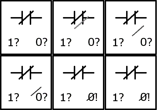
--| |-- and --|/|-- represent questions.

THESE ARE NOT CONTACTS! THEY ARE QUESTIONS!

--| |-- is asking... Is the Input Signal ON?

--|/|-- is asking... Is the Input Signal OFF?

The program doesn't give a hang what kind of contacts you are using in the field! The only thing the program wants to know is... Is the Input ON (--| |--)? Or, is the Input OFF (--|/|--)?

Maybe this will help you remember that the --|/|-- is looking for a Zero (Input OFF).
.
.
.
3e4d815665b7288e.gif

.
.
.
The answer to the question is either YES or NO.

--| |-- Is it ON?
If ON, then YES, It is ON!
If Not ON, then NO!

--|/|-- Is it OFF?
If OFF, then YES, It is OFF!
If Not OFF, then NO!

Now, knowing and understanding what Input-is-ON means and what Input-is-OFF means, for the particular Input, you simply need to ask the appropriate question.


--|?|--------(output)

Whatever the question is, if the answer is YES, then the Output turns ON!
 
PLC program works with process image of I/O-space. Process Image knows only if some I/O is true or false. RLO is Result of Locig Operation.

-] [- asks: if RLO is TRUE and Process image is TRUE then RLO is TRUE, other case RLO is FALSE

-]/[- asks: if RLO is TRUE and Process image is FALSE then RLO is TRUE, other case RLO is FALSE
 
About Process Image of physical I/O.

Usually PLC don't read directly the physical I/O in program scan it uses its Process image. The Image is the same in whole program scan time, so developer can be sure that it is not change among scan.
Ordinary PLC makes process image from Inputs 1'st, then it executes whole program and finally it updates Outputs from Process image.

Modern PLC dont scan whole inputs before every program scan. I/O units oncludes own processors and send process images if some Input have changed (as Event base system). This method releases CPU's recources and scanning time lowering for this reason. Also PLC updates only changed Outputs.

Same method (COS) is possible in DeviceNet Fieldbus, ControlNet controlbus, but not in ProfibusDB fielbus who scans fiel devices all the time and use unnecessoryly its recources, so its capacity is not comparable if only x nr. of bits/second is used.
 
Please do no drone on and on about this

My suggestion is get Phils book, this is a VERY simple aspect of working with plcs.
Clcik here to LEARN PLC's

Plc's were/are designed to replace relays therefore follow relay logic.

Its all based on electric flow. An input to a plc is either ON or OFF, the same would work with relays, if the device is on or off then the associated relay would be on/off.

There is a difference, a plc uses software but it emulates hardwiring. What it boils down to is that plc's use inputs (electrical flow thru a device) inputs to its ladder logic to determine when an output is on/off depending on the program.
 

Similar Topics

and then when i open the windowmaker, intouch is shutdown... that's not work that's demo I have 30days demo
Replies
3
Views
146
Hi All In my plc program in following picture there are functions FC50 in the begining and FC51 in end of organization block OB32. I can not...
Replies
3
Views
959
Just for readers in the US, when I write 'gas' I mean it as a state of matter, not shorthand for gasoline :-) I don't understand the logic of a...
Replies
39
Views
11,156
Hello all, I have recently been working on a project utilizing Allen Bradley PLC/HMI. It's an L16ER-BB1B PLC and a Panelview Plus 7 HMI. I'm...
Replies
15
Views
5,622
I’m using rslogix5000 v20 with ControlLogix L72. I added some rungs to monitor time meter of our propulsors. But with same ladder instruction I...
Replies
11
Views
4,002
Back
Top Bottom